Image processing system and camera

a technology of image processing and camera, applied in the field of image processing system and camera, can solve the problems of small and lightweight devices, and achieve the effect of improving the accuracy and reliability of the image processing system

Inactive Publication Date: 2008-10-23
OLYMPUS CORP
View PDF99 Cites 36 Cited by
  • Summary
  • Abstract
  • Description
  • Claims
  • Application Information

AI Technical Summary

Problems solved by technology

Further, these devices are also required to be small and lightweight and handy for the sake of examination operability.

Method used


Image

  • Image processing system and camera
  • Image processing system and camera
  • Image processing system and camera

Examples


first embodiment

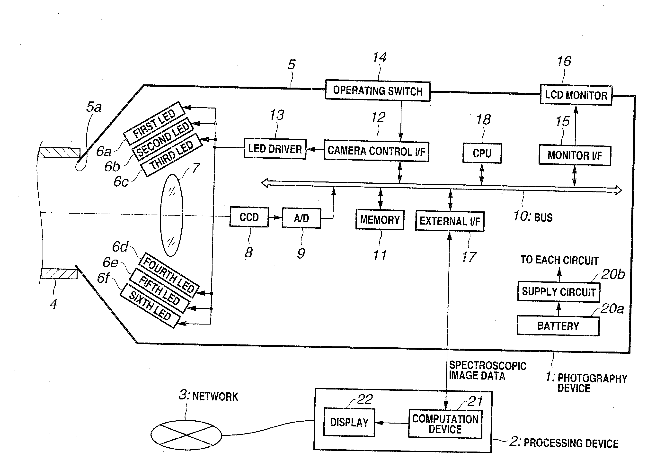
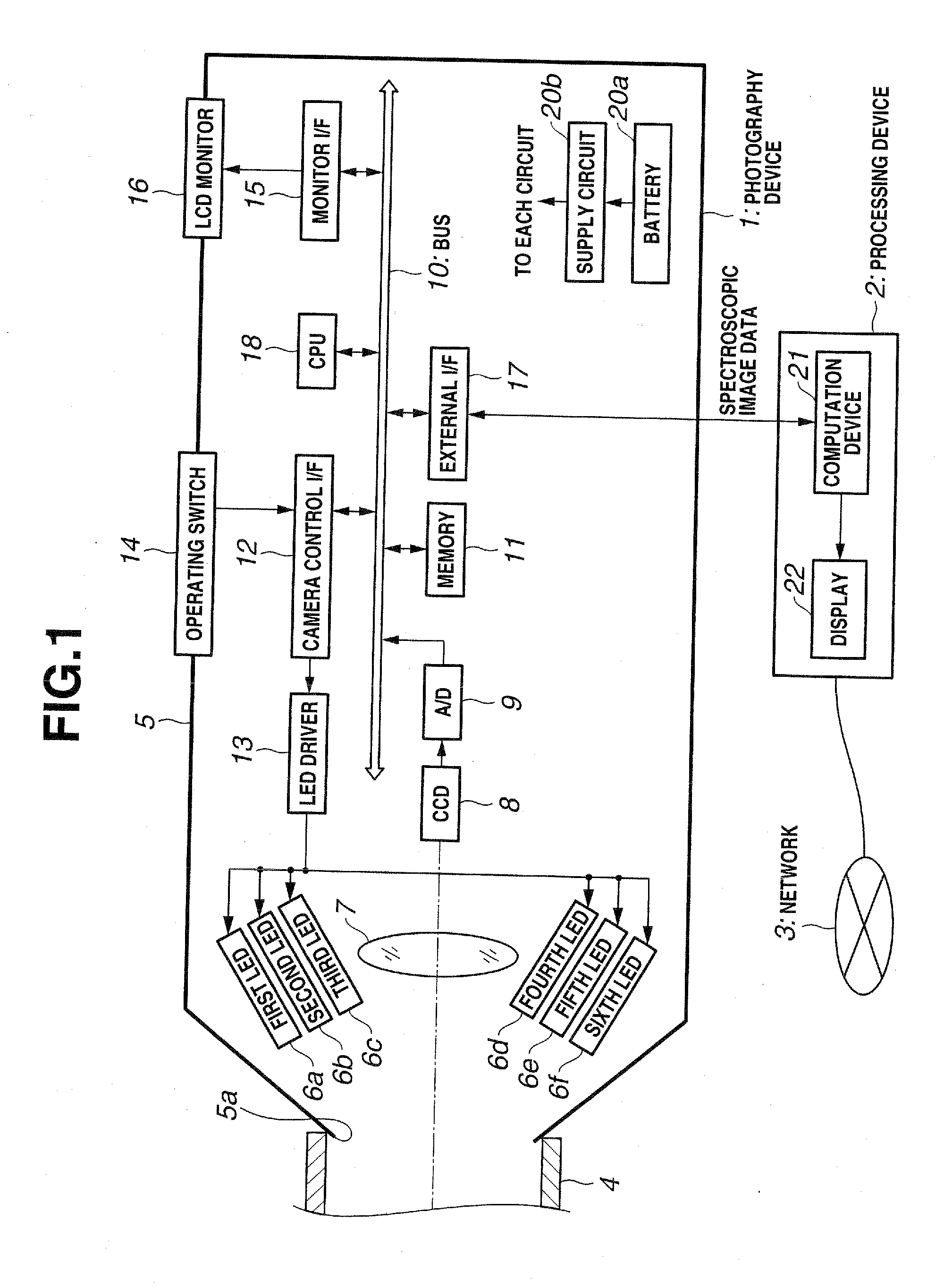
[0116]FIGS. 1 to 16, 70 to 88, and 99 show a first embodiment of the present invention and FIG. 1 is a block diagram showing the constitution of an image processing system.

[0117]This image processing system is constituted comprising a photography device 1 that is capable of photographing an object spectroscopic image by illuminating the object with illumination light of a plurality of different wavelength bands that are mutually independent in the range of visible light, and a processing device 2 that is connected to the photography device 1 and which processes an object spectroscopic image that is output by the photography device 1, wherein the processing device 2 is constituted such that the same can be connected to a network 3 if required.

[0118]In this embodiment, the photography device 1 is capable of performing: image pickup in which an installed light source is put in an illumination light lighting mode in order to use the same in the spectroscopic image acquisition, illuminat...

second embodiment

[0279]FIGS. 17 to 20 and FIG. 100 show a second embodiment of the present invention. FIG. 17 is a block diagram showing the constitution of the image processing system, FIG. 18A and FIG. 18B are timing charts that show reading aspects in full mode and reading two-speed mode in the second embodiment, FIG. 19A and FIG. 19B show aspects of lines read in 2 / 4 line two-speed mode and 2 / 8 line four-speed mode, and FIG. 20 is a flowchart showing the operation when the photography mode is set.

[0280]In this second embodiment, the same numerals are assigned to the parts that are the same as those of the first embodiment above and a description thereof will be omitted. Only the differences are mainly described.

[0281]The second embodiment has the basic constitution of the first embodiment described earlier and is constituted to permit the adjustment of the image reading speed from a color CCD that comprises a color filter array (CFA) 19 at the front face thereof.

[0282]The image reading speed is ...

third embodiment

[0317]FIGS. 21 to 36 show a third embodiment of the present invention. FIG. 21 is a block diagram showing the constitution of an image processing system and FIG. 22 shows an example of an aspect when the image processing system is used. In the third embodiment, the same numerals are assigned to the parts that are the same as those of the first and second embodiments above and a description of these parts will be omitted. Only the differences are mainly described.

[0318]The third embodiment has the basic constitution of the first embodiment described earlier and is constituted such that a three-band color filter array is installed on the photographic face of the CCD.

[0319]That is, as shown in FIGS. 21 and 22, the photography device 1 has an RBG 3-band color filter array (abbreviated as CFA in FIG. 21) 19 installed in the vicinity of the CCD 8 in the light path in which the object image is formed by the photography optical system 7 and a so-called single-panel-type color image pickup e...


PUM


Abstract

An image processing system which performs photography of the teeth of a patient while causing a plurality of illumination light LEDs of different wavelengths to emit light by means of a photography device when producing a crown repair or denture of the patient, whereby image data are acquired. The image data are transmitted to a dental filing system constituting a processing device where color reproduction data are determined through computation. In addition, color reproduction data are transmitted to the dental technician's office via a public switched network. A repair material compound ratio calculation database is searched and compound data for a material that matches the hue of the patient's teeth is retrieved, so that a crown repair or denture or the like that very closely matches the color of the patient's teeth can be produced.

Description

CROSS REFERENCE TO RELATED APPLICATION[0001]The present application is a Divisional Application of U.S. application Ser. No. 11 / 486,455 filed Jul. 13, 2006, which is a continuation application of PCT / JP2005 / 000783 filed on Jan. 21, 2005 and claims benefit of Japanese Application No. 2004-016264 filed in Japan on Jan. 23, 2004, the entire contents of which are incorporated herein by this reference.BACKGROUND OF THE INVENTION[0002]1. Field of the Invention[0003]The present invention relates to an image processing system and camera that acquire a spectroscopic spectral image information on an object, and perform highly accurate color reproduction, examination, and judgment and so forth on an image of the object from the acquired image information.[0004]2. Description of the Related Art[0005]In recent years, there has been a growing interest in health and an increased need for whitening due to the pursuit of beauty. Conventionally, diagnoses using skin diagnosis cameras have been provid...

Claims


Application Information

Patent Timeline
Patent Type & Authority Applications(United States)
IPC IPC(8): G01J3/40A61B5/00G01J3/02G01J3/10G01J3/50G03B15/00
CPCA61B5/4547G01J3/02G01J3/0218G01J3/0224G01J3/0264G01J3/0272G01J3/0291G01J3/10G01J3/50G01J3/501G01J3/508G01J3/51A61B5/0013
Inventor KONNO, OSAMUKOMIYA, YASUHIROWADA, TORUSATO, NOBUMASA
Owner OLYMPUS CORP
Why Eureka
Try Eureka