Television receiving apparatus

Inactive Publication Date: 2009-02-26
DX ANTENNA CO LTD +2
View PDF7 Cites 0 Cited by
  • Summary
  • Abstract
  • Description
  • Claims
  • Application Information

AI Technical Summary

Benefits of technology

[0011]The present invention has been made in view of the foregoing problems and it is therefore an object of the present invention to provide a television receiving apparatus provided with an antenna having radio wave receiving directivity capable of being electrically changed and of being disposed so as to improve the appearance and to improve signal receiving sensitivity.
[0014]Thus, according to the present invention, the antenna disposed near the television receiver is invisible, and the antenna can be disposed at the predetermined distance from the television receiver. Therefore, in disposing the antenna having directivity capable of being electrically changed so as to match with radio waves to be received, the aesthetic appearance can be improved and the signal receiving sensitivity of the antenna can be improved.
[0015]In the television receiving apparatus according to the present invention, the antenna holding box may include an antenna holding part holding the antenna with a receiving device forming the antenna set such that signal receiving directions from which the receiving device receives signals are horizontal, shafts each having a first end connected to the antenna holding part and a second end mounted on the television receiver so as to be slidable to change the distance between the antenna holding part and the television receiver, and a fixing mechanism for fixing the shaft to the television receiver such that the antenna holding part is at the predetermined distance from the television receiver. The antenna can be held easily in the antenna holding box and can be disposed at the predetermined distance from the television receiver.
[0016]In the television receiving apparatus according to the present invention, the antenna can be easily held in the antenna holding box and can be disposed at the predetermined distance from the television receiver. Therefore, the aesthetic appearance can be properly improved and the signal receiving sensitivity of the antenna can be properly improved.
[0021]In the television receiving apparatus according to the present invention, the antenna holding box may include an antenna holding part holding plural broadcast digital signal receiving devices forming the antenna with the respective signal receiving directions of the plural signal receiving devices extended in a horizontal plane, and two shafts each having a first end connected to the antenna holding part and a second end mounted on the television receiver so as to be slidable to change the distance between the antenna holding part and the television receiver, and a fixing mechanism for fixing the shafts to the television receiver such that the antenna holding part is at the predetermined distance from the television receiver, wherein a section in a horizontal plane of the antenna holding part is substantially elliptic, the respective first ends of the two shafts are connected to opposite ends apart separated from each other of the antenna holding part, the respective second ends of the shafts can be partly or entirely received in the television receiver, and the antenna holding box may be a handle attached to an upper part of the television receiver provided with a 15 to 23 in. display screen. Thus, the antenna can be held in the handle and can be easily separated from the television receiver by the predetermined distance.
[0022]According to the present invention, the antenna can be easily held in the handle and can be easily separated from the television receiver by the predetermined distance. Therefore, the handle can function as the antenna (or the antenna can be used as the handle), the aesthetic appearance can be properly improved and the signal receiving sensitivity of the antenna can be properly improved. The television receiver provided with a 15 to 23 in. display screen can be easily carried by hand.

Problems solved by technology

When the smart antenna is disposed in a manner mentioned above, it is possible that the smart antenna and the antenna cable spoil the aesthetic appearance of the television receiving apparatus.
Although the aesthetic appearance is not spoiled by incorporating the smart antenna into the television receiver as mentioned in Patent documents 2 or 3, it is difficult to arrange the receiving devices horizontally and to dispose the receiving devices at the predetermined distance from the television receiver and it is possible that the signal sensitivity of the smart antenna is reduced.
Thus, the improvement of the aesthetic appearance and the improvement of the signal sensitivity of the smart antenna are contradictory to each other.

Method used


Image

  • Television receiving apparatus
  • Television receiving apparatus
  • Television receiving apparatus

Examples


Embodiment Construction

[0029]A preferred embodiment of the present invention will be described with reference to the accompanying drawings.

[0030](1) General Construction of Television receiving apparatus

[0031](2) Construction of Antenna holding box

[0032](3) Modifications

[0033](4) Summary

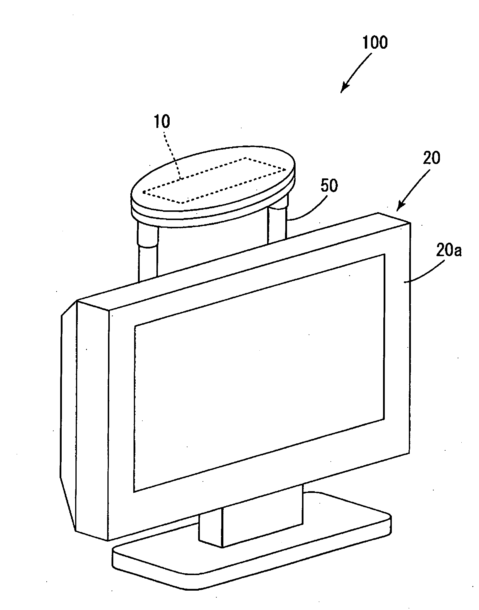
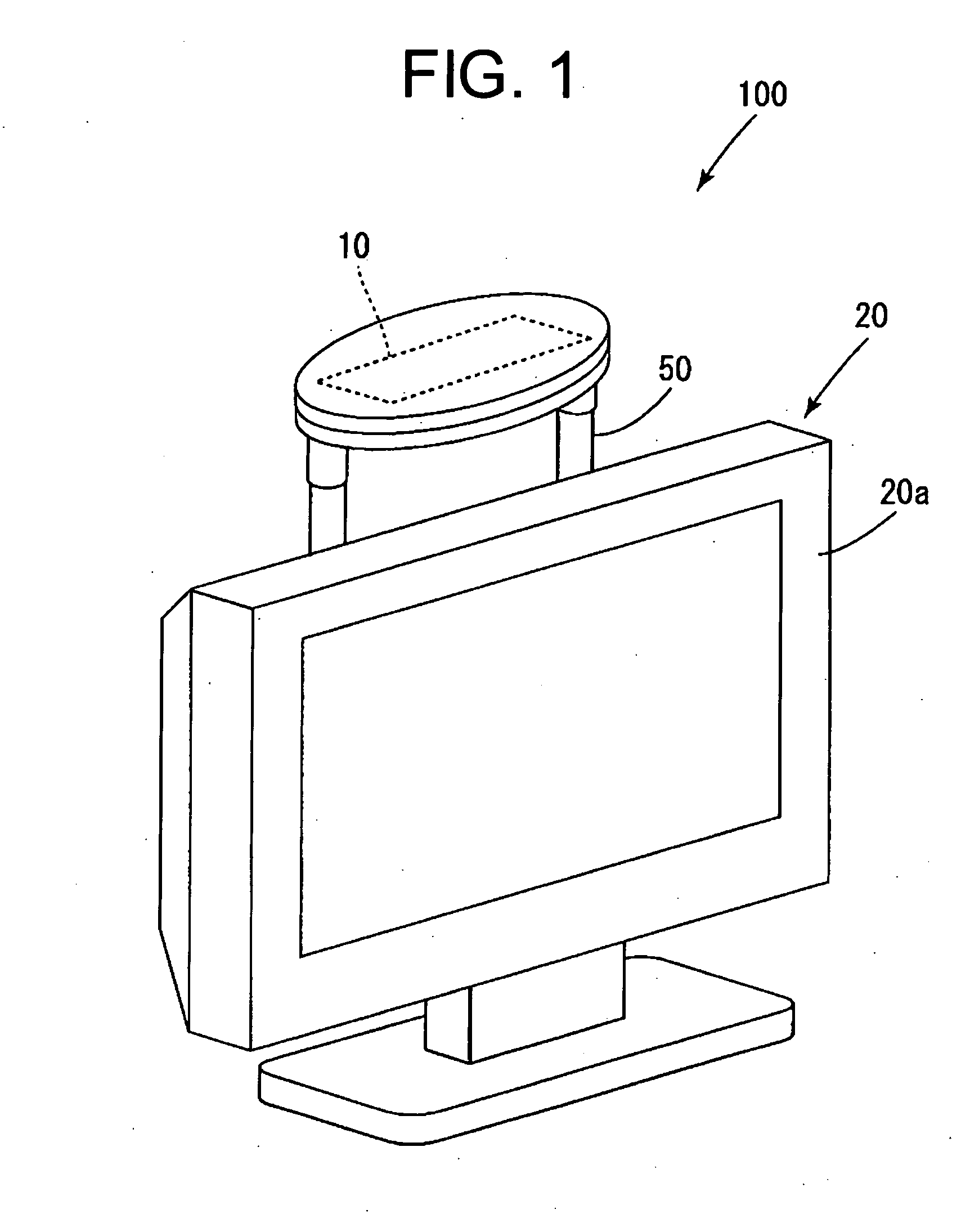
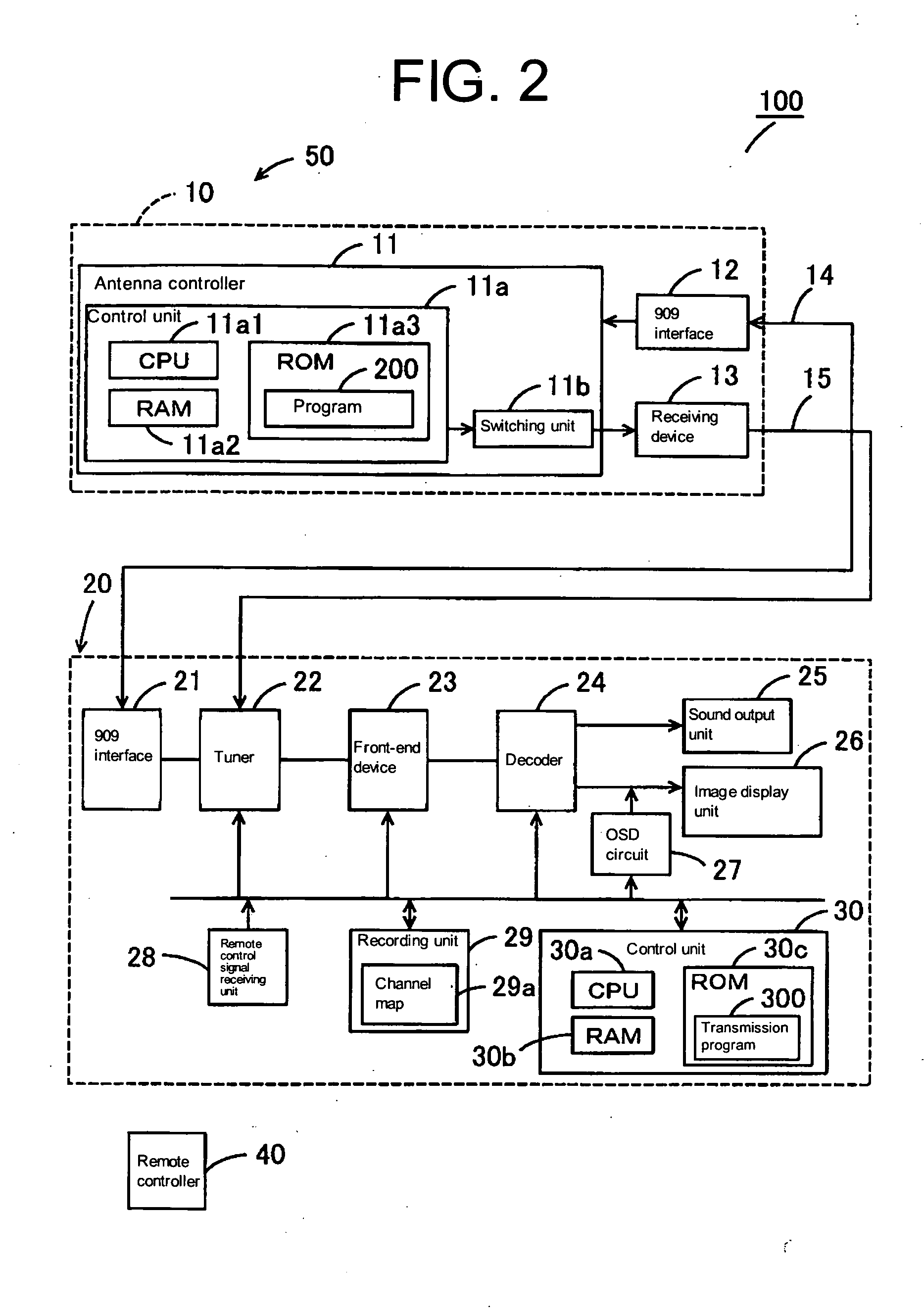
[0034](1) General Construction of Television receiving apparatus The general construction of a television receiving apparatus 100 in a preferred embodiment according to the present invention will be described with reference to FIGS. 1 and 2. FIG. 1 is a perspective view of the television receiving apparatus 100 and FIG. 2 is a block diagram of the television receiving apparatus 100. Referring to FIGS. 1 and 2, the television receiving apparatus 100 includes a handle 50 serving also as an antenna holding box holding a smart antenna 10, and a television receiver 20. The smart antenna 10 is connected to the television receiver 20 through an interface (hereinafter, referred to as “909 interface”) for communication on the basis...


PUM


Abstract

A television receiving apparatus 100 includes a television receiver 20, and a smart antenna 10 having directivity capable of being electrically changed so as to match radio waves to be received. A handle 50 is provided with a mechanism holding the smart antenna 10 therein, fixed to the television receiver 20 and capable of changing the distance between the smart antenna 10 and the television receiver 20 as an antenna holding box. The antenna having directivity capable of being electrically changed so as to match with radio waves to be received is disposed so that the aesthetic appearance can be improved and the signal receiving sensitivity of the antenna can be enhanced.

Description

CROSS-REFERENCES TO RELATED APPLICATIONS[0001]The entire disclosure of Japan Patent Application No. 2007-216292, filed Aug. 22, 2007, is expressly incorporated by reference herein.BACKGROUND OF THE INVENTION[0002]1. Field of the Invention[0003]The present invention relates to a television receiving apparatus capable of receiving broadcast television signals and of reproducing images and associated sounds and, more particularly, to a television receiving apparatus provided with an antenna having changeable directivity.[0004]2. Description of the Related Art[0005]A known television receiving apparatus is provided with an antenna having directivity capable of being electrically changed so as to match with radio waves to be received, namely, an antenna commonly called a “smart antenna”. For example, a television receiving apparatus disclosed in JP-A 2005-354631 (hereinafter, referred to as “Patent document 1”) is such a television receiving apparatus. According to Patent document 1, a s...

Claims


Application Information

Patent Timeline
IPC IPC(8): H01Q1/24
CPCH01Q3/00H01Q1/42
Inventor NAKAJIMA, NOBUOGYODA, KOICHISHIBUYA, EIJIONOMATSU, TAKEHIROYOSHIMURA, HIDETO
Owner DX ANTENNA CO LTD
Why Eureka
Try Eureka