
Rotary clip rotation mechanism for air gun
a rotation mechanism and air gun technology, applied in the field of rotary clips, can solve the problems of the mechanism of rotating the rotary clip, the rotary clip itself, the inability to rotate the rotary clip, etc., and achieve the effects of reducing the degradation and reducing the damage of the nail, and improving durability
- Summary
- Abstract
- Description
- Claims
- Application Information
AI Technical Summary
Benefits of technology
Problems solved by technology
Method used
Image

Examples
Embodiment Construction
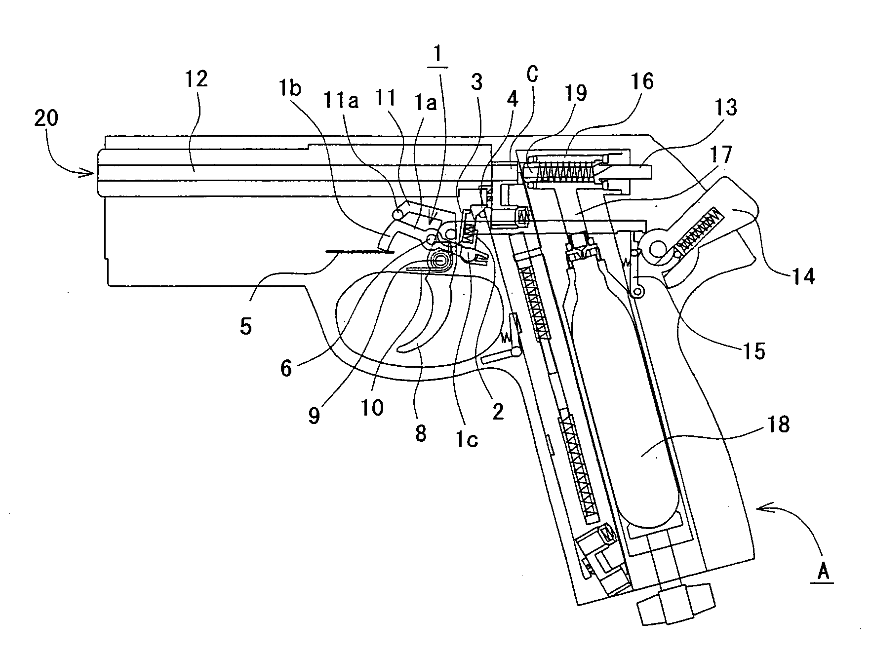
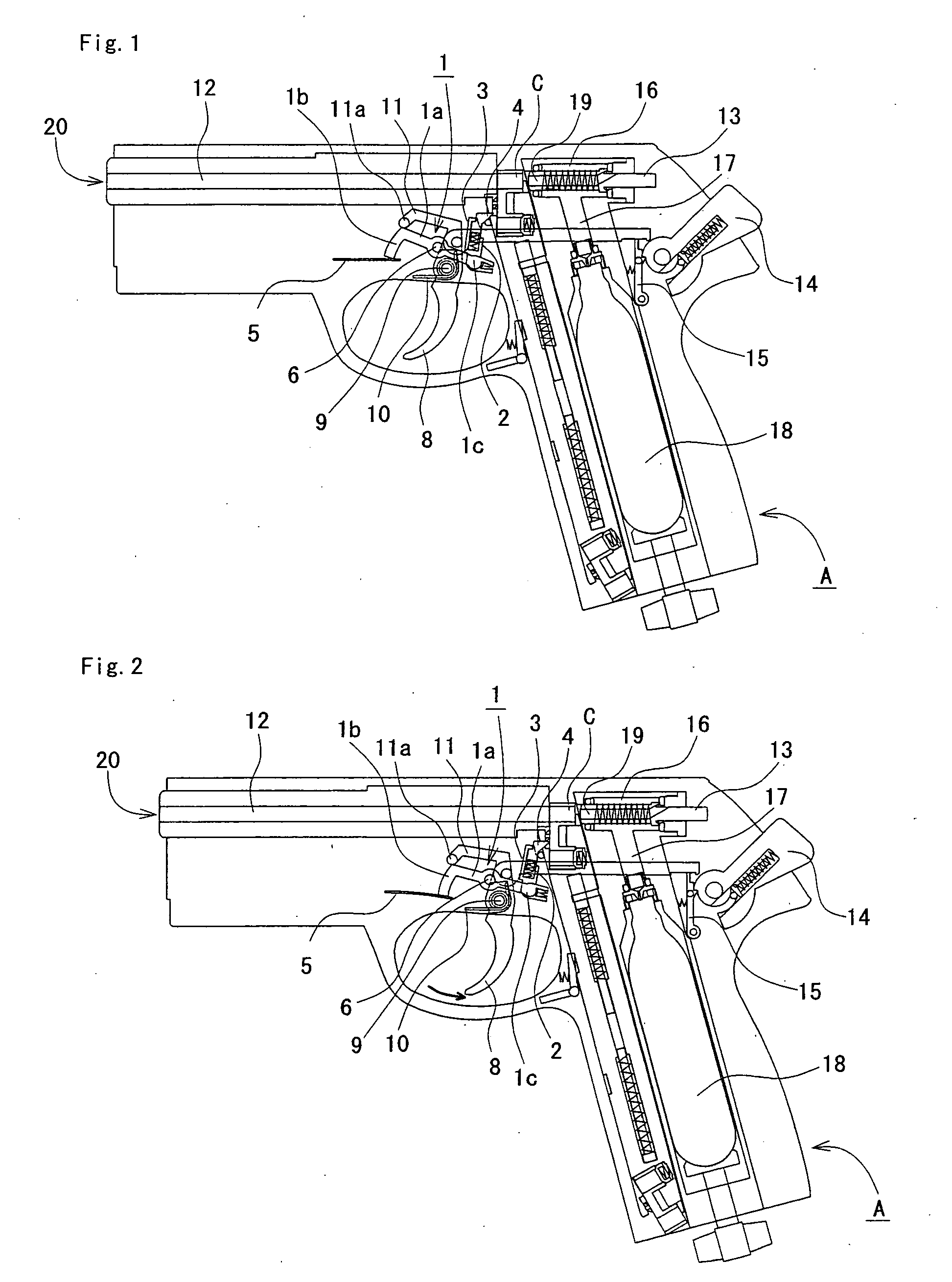
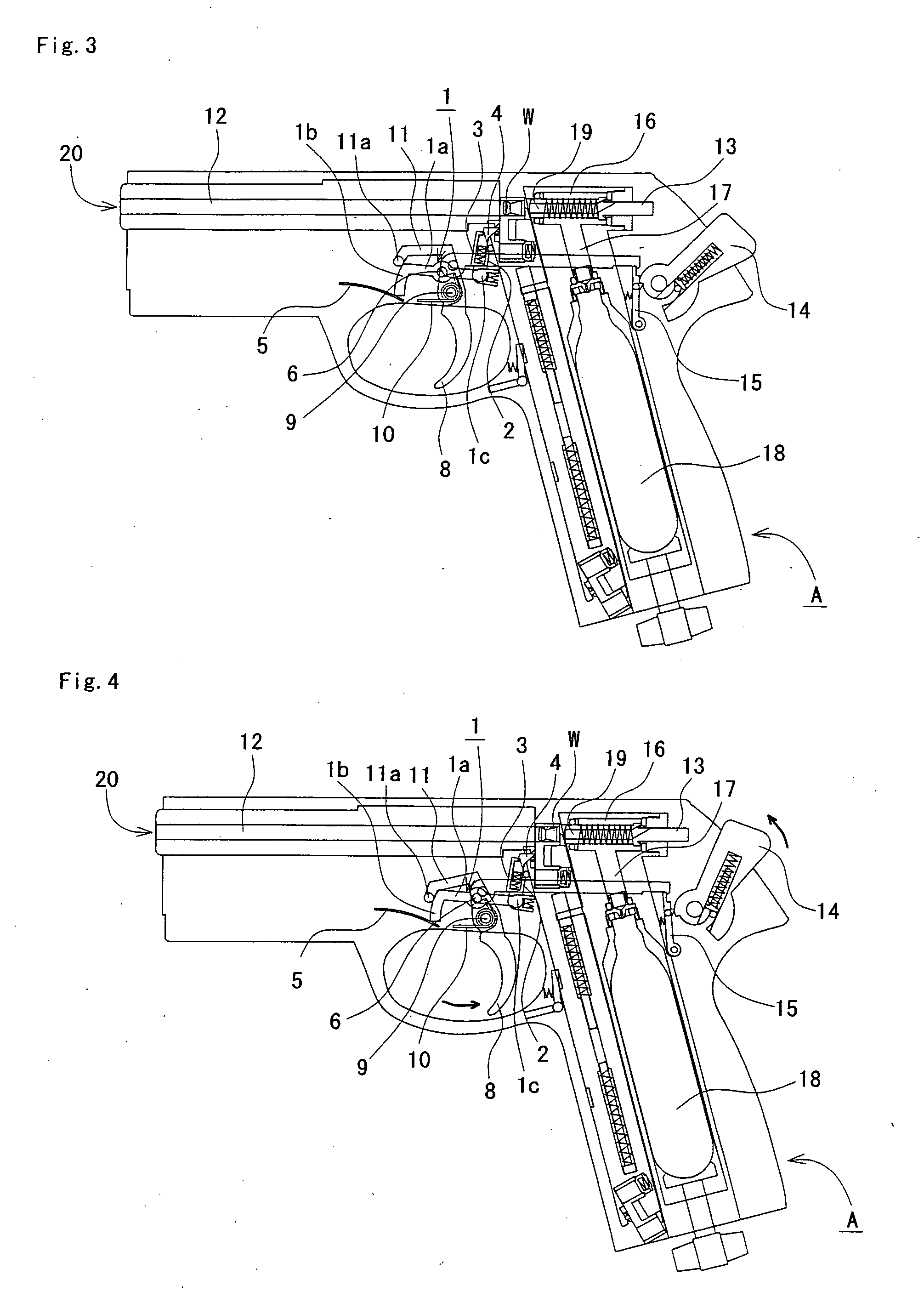
[0043]For a rotary clip rotation mechanism for an air gun of an embodiment of the present invention, FIG. 1 to FIG. 5 show normal operation at the time of successfully rotating a rotary clip. FIG. 1 is a central cross-sectional explanatory drawing of an air gun showing, in a rotary clip rotation mechanism of an air gun of an embodiment of the present invention, a state where a hammer is moved to the gun rear end side and bullets can be fired by pulling the trigger, FIG. 2 is a central cross-sectional explanatory drawing of an air gun showing a state immediately after pulling a trigger from FIG. 1, FIG. 3 is a central cross-sectional explanatory drawing of an air gun showing a state immediately after pulling a trigger further back than FIG. 2, FIG. 4 is a central cross-sectional drawing of an air gun showing a state after FIG. 3, where a hammer starts to advance, and FIG. 5 is a central cross-sectional drawing of an air gun showing a state, after FIG. 4, immediately after firing a bu...
PUM
 Abstract
Description
Claims
Application Information