Focus control device and imaging device

Inactive Publication Date: 2009-03-12
SONY CORP
View PDF3 Cites 15 Cited by
  • Summary
  • Abstract
  • Description
  • Claims
  • Application Information

AI Technical Summary

Benefits of technology

[0020]According to the invention as defined in any one of claims 2 and 3 as well, the focusing position of the optical lens is detected by preferentially using evaluation values acquired by using a predetermined filter of the plurality of filters which emphasizes and extracts relatively high frequency band components. Therefore, for example, it is possible to perform focusing control in conformity to the human visual characteristic of perceiving a subject image as being sharper when high frequency components increase, thereby enabling high-precision focusing control.
[0021]According to the invention as defined in claim 4, the focusing position of the optical lens is detected by preferentially using evaluation values acquired by using a predetermined filter having a frequency characteristic of emphasizing and extracting predetermined frequency band components relative to other filters of the plurality of filters. Therefore, for example, it is possible to perform focusing control with an emphasis on predetermined high frequency band components that increase when a captured image of a typical subject is in focus, thereby enabling high-precision focusing control.
[0022]According to the invention as defined in claim 5, light from a subject is split into two optical paths, and focusing control based on the phase difference method and focusing control based on the contrast method are carried out in parallel by using the respective split light beams. Accordingly, for example, it is possible to drive the optical lens to the vicinity of the lens focusi

Problems solved by technology

However, according to the technique proposed in Japanese Unexamined Patent Application Publication No. 05-3

Method used


Image

  • Focus control device and imaging device
  • Focus control device and imaging device
  • Focus control device and imaging device

Examples


Example

[0045]An embodiment of the present invention will now be described with reference to the drawings.

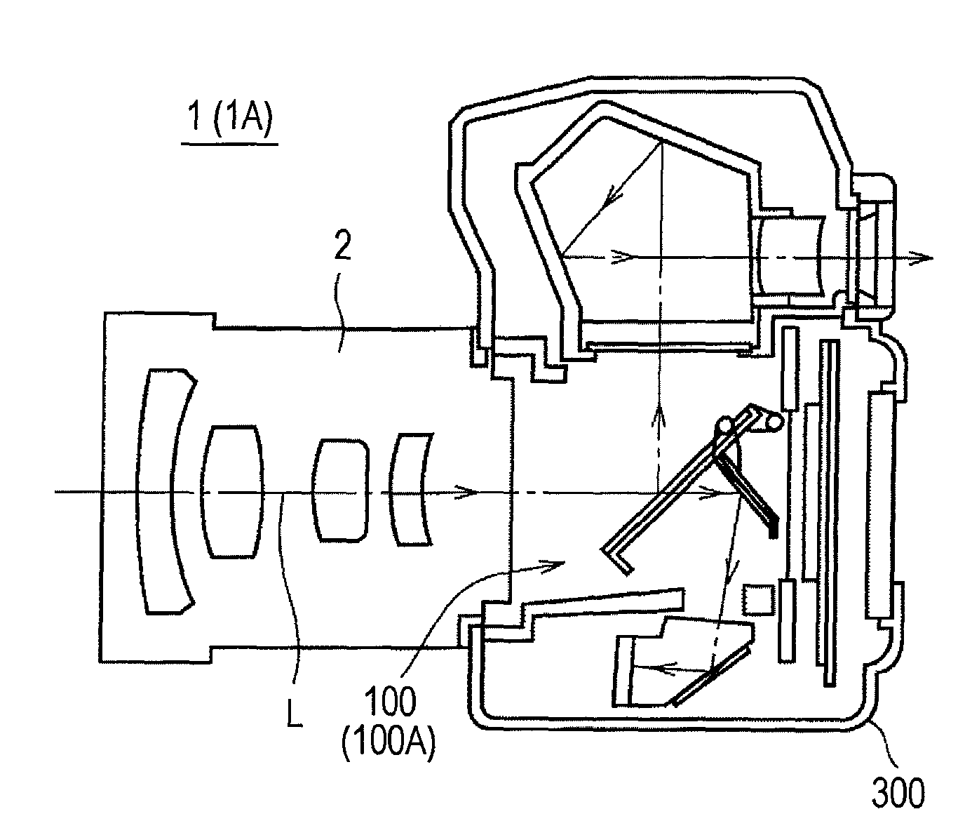
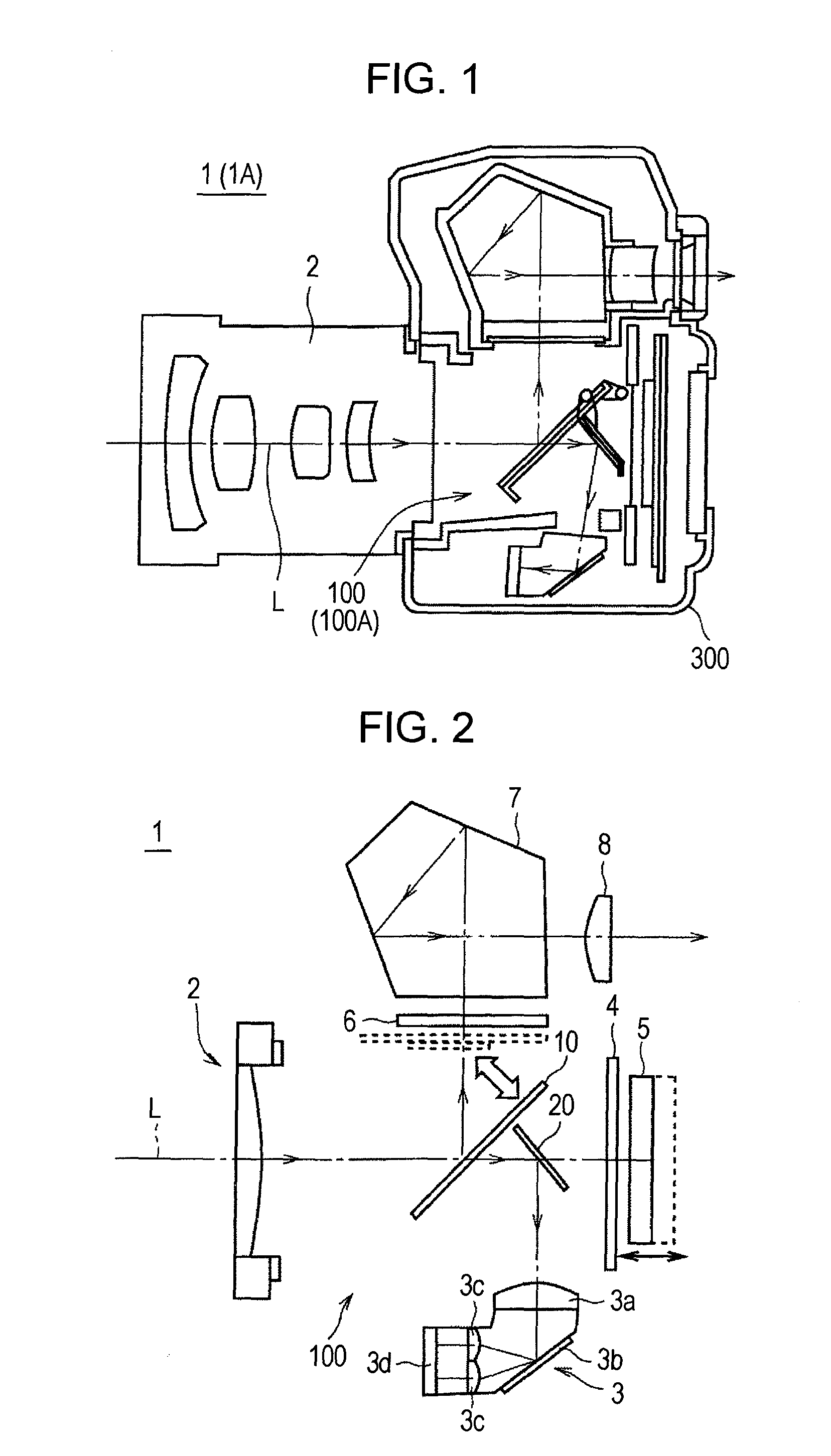
[0046]FIG. 1 is a schematic sectional view showing the general configuration of an imaging apparatus 1 according to an embodiment of the present invention

[0047]As shown in FIG. 1, the imaging apparatus 1 is configured as a so-called single-lens reflex digital camera, with which captured image data (captured image) associated with a subject can be obtained by guiding light from the subject to an imaging apparatus body 300 via a taking lens unit 2. A unit (hereinafter referred to as “AF control unit” as well as “focusing control device”) 100 for performing an auto-focus (AF) control in the imaging apparatus 1 is mounted in the imaging apparatus body 300. In the taking lens unit 2, a lens group having a plurality of taking lenses including lenses (focus lenses) for realizing AF control are disposed on the optical axis L of the taking lens unit 2.

[0048]FIG. 2 is a schematic view focusing on...


PUM


Abstract

An auto focus (AF) circuit includes a high-pass filter and band-pass filter having mutually different frequency characteristics. During contrast AF control prior to an actual shooting, AF evaluation values acquired by using the high-pass filter are used most preferentially in detecting the lens focusing position of a focus lens. In this way, the high-pass filter that emphasizes and extracts high frequency band components, which increase in image data when shooting a typical subject, is set to be used preferentially, thereby making it possible to perform high-precision focusing control with respect to various kinds of subjects.

Description

TECHNICAL FIELD[0001]The present invention relates to a focusing control technique.BACKGROUND ART[0002]In the related art, a so-called phase difference method is often adopted for the auto focus (AF) control carried out in imaging apparatuses such as a silver-halide film camera. However, it is known that the precision of AF control based on this phase difference method is not good, particularly when shooting at a small f-stop.[0003]On the other hand, in recent years, with the advent of digital cameras, imaging apparatuses adopting AF control based on a so-called contrast method (hill climbing method) have become widespread. It is known that AF control based on the contrast method provides higher AF precision than AF control based on the phase difference method.[0004]Accordingly, it is conceivable to achieve improved AF precision by using AF control based on the phase difference method and AF control based on the contrast method in combination.[0005]Incidentally, AF control based on ...

Claims


Application Information

Patent Timeline
IPC IPC(8): H04N5/232
CPCG02B7/365G03B13/36H04N2101/00H04N5/772H04N5/23212H04N23/672H04N23/673
Inventor FUJII, SHINICHIAKAMATSU, NORIHIKOAOYAMA, JUNSHINTANI, DAINAKAJIMA, HIDEKAZU
Owner SONY CORP
Why Eureka
Try Eureka