
Imaging device and method for calculating focus parameter values

A technology of parameter values ​​and pixels, applied in the field of image capture devices, can solve problems such as the influence of the focus accuracy of photographic lenses, and achieve the effect of high-precision focus control

Active Publication Date: 2016-01-27
FUJIFILM CORP
View PDF7 Cites 0 Cited by
  • Summary
  • Abstract
  • Description
  • Claims
  • Application Information

AI Technical Summary

Problems solved by technology

[0005] In an image capture device equipped with an image capture element including phase difference pixels, when the image capture device is a lens replacement type image capture device, due to factors such as the placement position of the phase difference pixels on the image capture device or the distance between a pair of pixels The physical conditions of the interval cannot be changed, so when the photographic lens is replaced, the focusing accuracy of the photographic lens is affected

Method used


Image

  • Imaging device and method for calculating focus parameter values
  • Imaging device and method for calculating focus parameter values
  • Imaging device and method for calculating focus parameter values

Examples


Embodiment Construction

[0030] Hereinafter, embodiments of the present invention will be described with reference to the accompanying drawings.

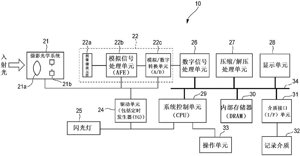
[0031] figure 1 A block diagram is a schematic configuration of a digital camera (image capturing device) according to an embodiment of the present invention. This digital camera 10 includes a photographing optical system 21 including a photographing lens 21 a or a diaphragm 21 b and an image capturing element chip 22 arranged on a subsequent stage of the photographing optical system 21 . The photographing optical system 21 is replaceably mounted, and a user can select a desired photographing optical system (wide-angle lens system, telephoto lens system, etc.).

[0032] The image capture element chip 22 includes a single-plate type solid-state image capture element 22a, such as a CCD type or a CMOS type, as a signal reading device for capturing a color image, an analog signal processing unit (AFE) 22b, The analog signal processing unit performs analog pro...


PUM


Abstract

An imaging device, comprising: an imaging element having a plurality of pixels and a phase difference pixel, wherein the plurality of pixels are arranged in a two-dimensional array pattern, and the phase difference pixel is formed in an effective pixel area; an imaging lens A phase difference detection unit, the phase difference detection unit analyzes the image signal captured by the imaging element, and finds the phase difference from the detection signals of the paired two phase difference pixels; and a control unit, the control The unit finds the defocus amount for the photographic subject image captured by the imaging element from the detected phase difference amount, and performs focus control on the imaging lens. The control unit: finds a parameter value related to a ratio between a defocus amount and a phase difference amount and finds a defocus amount based on imaging lens information for an imaging lens and a light-receiving sensitivity distribution for Sensitivity for each incident angle of incident light with respect to a pair of two phase difference pixels.

Description

technical field [0001] The invention relates to an image capture device comprising an image capture element with phase difference pixels and a method for calculating a focus parameter value. Background technique [0002] Some of the plurality of pixels formed and arranged in a two-dimensional array pattern in the light receiving area are formed by phase difference pixels (also referred to as focus detection pixels) mounted in an image sensor within an image capture device (camera). A phase difference AF method is adopted in an image capture device mounted with an image capture element as an AF method for adjusting the focus position of a photographic lens to a photographic subject. [0003] The phase difference pixel has a structure in which the phase difference pixel is divided into one pixel and the other pixel in a pair of pixels by a pupil, and one pixel receives one of two lights passing through different optical paths of the photographing lens, And another pixel recei...

Claims


Application Information

Patent Timeline
Patent Type & Authority Patents(China)
IPC IPC(8): G02B7/28G02B7/34G03B13/36H04N5/232
CPCG02B7/28G02B7/34H04N23/672H04N25/704H04N25/134
Inventor 井上和纪青木贵嗣
Owner FUJIFILM CORP
Learn More