Capacitive Touch Panel with Low Coupling Capacitance and Display Device Using the Capacitive Touch Panel

Active Publication Date: 2009-04-02
AU OPTRONICS CORP
View PDF13 Cites 32 Cited by
  • Summary
  • Abstract
  • Description
  • Claims
  • Application Information

AI Technical Summary

Benefits of technology

[0013]In order to reduce the lateral capacitance between the adjacent X and the second electrodes or between adjacent first electrodes, the width of the first electrodes is reduced from the middle of the first electrode to two sides of the first electrode along the second direction. This above-mentioned design reduces the effective overlapping area for generating capacitance between first electrodes and the adjacent second electrode or between first electrodes on the adjacent first direction electrode strings. This reduction in the effective overlapping area in turn reduces the lateral capacitance between electrodes.
[0014]Each of the first electrodes has a perimeter forming the shape of the first electrode. Each first electrode is surrounded by four adjacent second

Problems solved by technology

However this type of touch panel 30 cannot process multi-input simultaneously and also cannot process fingerprint recognition.
As the lateral capacita

Method used


Image

  • Capacitive Touch Panel with Low Coupling Capacitance and Display Device Using the Capacitive Touch Panel
  • Capacitive Touch Panel with Low Coupling Capacitance and Display Device Using the Capacitive Touch Panel
  • Capacitive Touch Panel with Low Coupling Capacitance and Display Device Using the Capacitive Touch Panel

Examples


Embodiment Construction

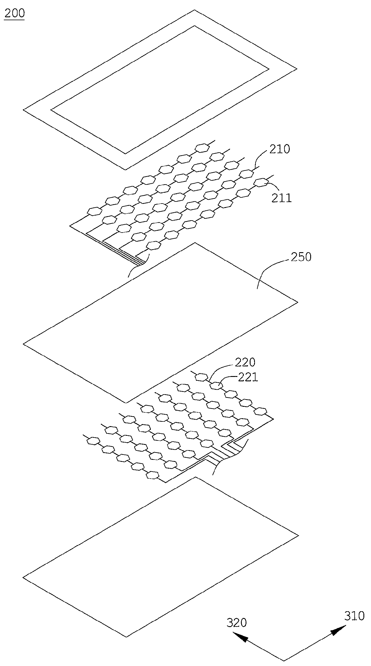
[0024]The present invention provides a capacitive touch panel and a display device using the capacitive touch panel. The said display device includes flat panel display devices using display panels but is not limited thereto. Furthermore, the liquid crystal display panel includes transmissive liquid crystal display panels, reflective liquid crystal display panels, transflective liquid crystal display panels and other types of liquid crystal display panels.

[0025]In the embodiment shown in FIG. 2, the display device 100 includes a display panel 110 and a capacitive touch panel 200. The capacitive touch panel 200 is preferred to be disposed on a display surface 111 of the display panel 110. The images on the display surface 111 of the display panel 100 are displayed outwards through the capacitive touch panel 200. When the user physically points at the displayed images on the display surface 111. The capacitive touch panel 200 determines the contact point by the user and outputs a sign...


PUM


Abstract

A capacitive touch panel and a display device using the capacitive touch panel are provided. The capacitive touch panel includes a plurality of first direction electrode strings and second direction electrode strings. Each first direction electrode string has a plurality of first electrodes while each second direction electrode has a plurality of second electrodes. In order to reduce the lateral capacitance between adjacent electrodes, width of the first electrode is reduced from the middle to two sides of the electrode along a second direction. In addition, the first electrode has a perimeter surrounding itself. Each quarter of the perimeter of the first electrode facing the adjacent second electrode has a first slope change rate and a different second slope change rate.

Description

BACKGROUND OF THE INVENTION[0001]1. Field of the Invention[0002]The present invention relates to a capacitive touch panel and a display device using the capacitive touch panel. Specifically, the present invention relates to a capacitive touch panel having low coupling capacitance and a display device using the capacitive touch panel.[0003]2. Description of the Prior Art[0004]Display panels and flat screen display device using the display panels are gradually becoming the mainstream in the field of display devices. For instance, flat television for home use, liquid crystal display of the personal computer or of the laptop computer, display screen of mobile phone and digital camera are products incorporating the display panel as one essential component. As the product design is gradually becoming user-oriented, the usability for the user and the touch input function of the display panel become an emphasis in the development of display device industry.[0005]As FIG. 1a shows, a conventi...

Claims


Application Information

Patent Timeline
IPC IPC(8): G06F3/044
CPCG06F3/044G06F3/0445G06F3/0446
Inventor YANG, TUN-CHUNLEE, SEOK-LYULHU, CHIH-JEN
Owner AU OPTRONICS CORP
Why Eureka
Try Eureka