Variable valve lift apparatus

a technology of valve lift and valve body, which is applied in the direction of valve details, non-mechanical valves, valve arrangements, etc., can solve the problems of insufficient valve open time and amount for low driving speed, engine not running at its optimal state, and inability to adjust the amount of gas being introduced or exhausted, etc., to achieve the effect of simple design chang

Inactive Publication Date: 2009-04-09
HYUNDAI MOTOR CO LTD
View PDF7 Cites 6 Cited by
  • Summary
  • Abstract
  • Description
  • Claims
  • Application Information

AI Technical Summary

Benefits of technology

[0023]A variable valve lift apparatus according to an exemplary embodiment of the present invention is configured with simple elements, uses hydraulic pressure to selectively connect an inner body and...

Problems solved by technology

Therefore, it is impossible to adjust the amount of a gas that is being introduced or exhausted.
Therefore, the engine does not run at its optimum state in various driving ranges.
For examp...

Method used


Image

  • Variable valve lift apparatus
  • Variable valve lift apparatus
  • Variable valve lift apparatus

Examples


Embodiment Construction

[0037]Hereinafter reference will now be made in detail to various embodiments of the present invention, examples of which are illustrated in the accompanying drawings and described below. While the invention will be described in conjunction with exemplary embodiments, it will be understood that present description is not intended to limit the invention to those exemplary embodiments. On the contrary, the invention is intended to cover not only the exemplary embodiments, but also various alternatives, modifications, equivalents and other embodiments, which may be included within the spirit and scope of the invention as defined by the appended claims.

[0038]Exemplary embodiments the present invention will be described more fully hereinafter with reference to the accompanying drawings.

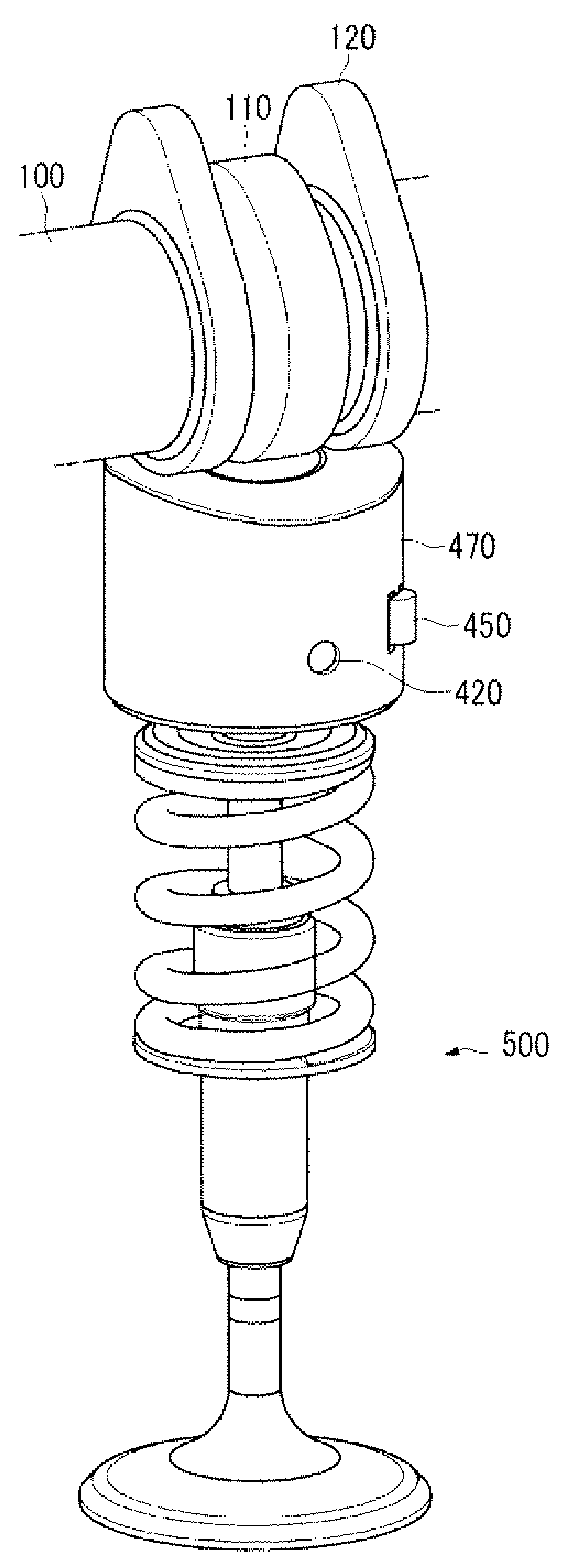
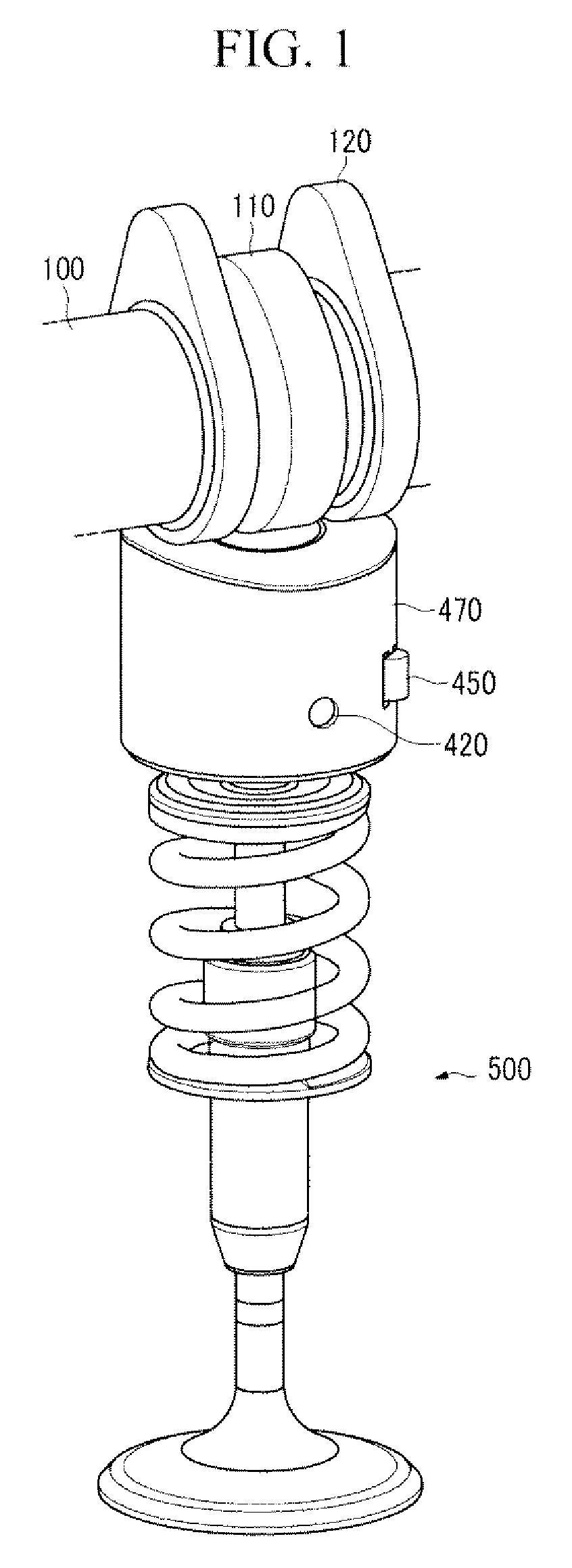
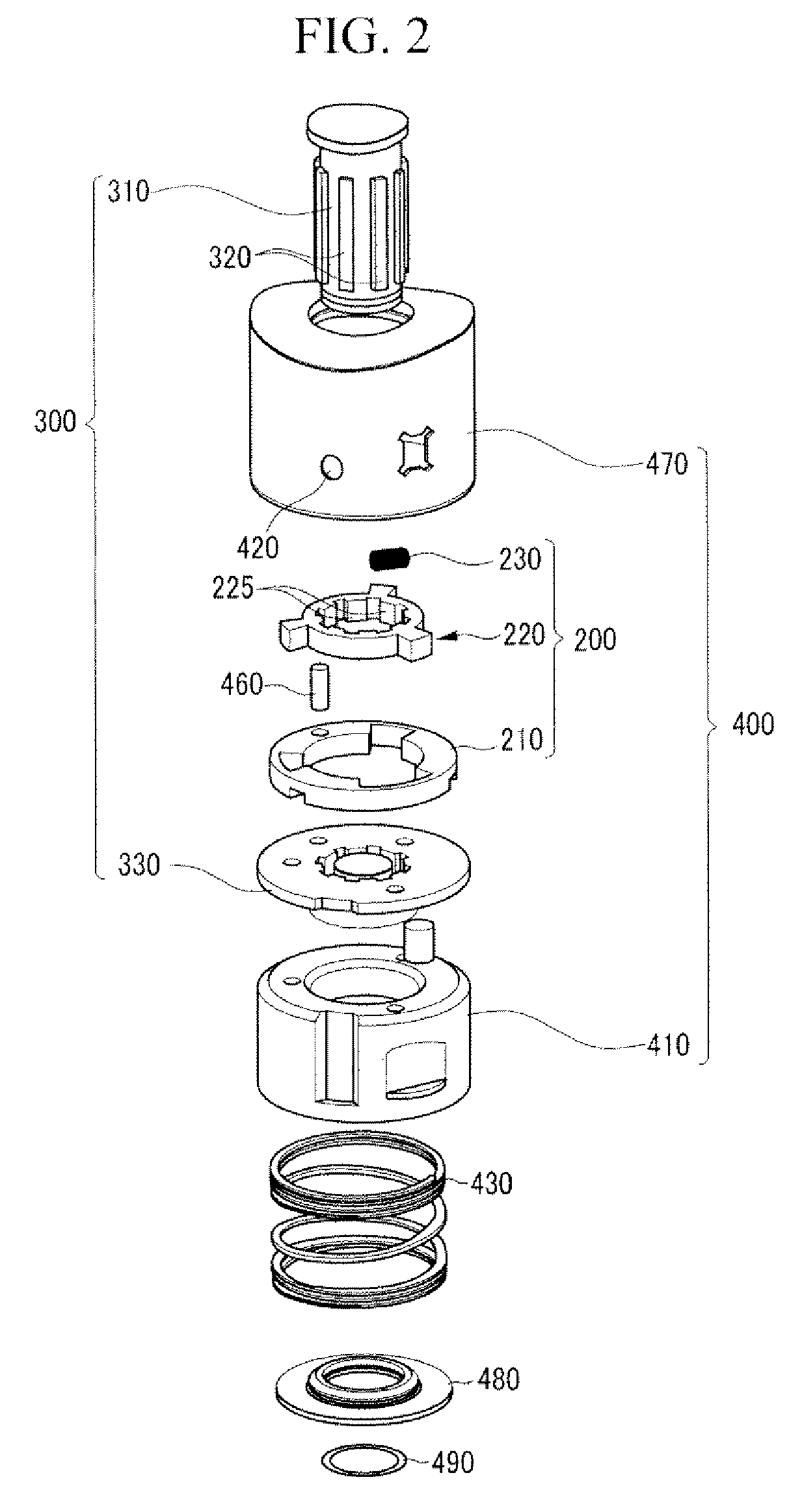
[0039]FIG. 1 is a perspective view of a variable valve lift apparatus according to an exemplary embodiment of the present invention, and FIG. 2 is an exploded view of a variable valve lift apparatus accord...


PUM


Abstract

A variable valve lift apparatus according to an exemplary embodiment of the present invention may include an outer part, an inner part disposed in the outer part and connected to a valve, a latching part that is disposed in the outer part and selectively connects the outer part and the inner part, a camshaft supplying torque, a low lift cam that is configured to the camshaft and selectively supplies torque to the inner part, and a high lift cam that is configured to the camshaft and supplies torque to the outer part.

Description

CROSS-REFERENCE TO RELATED APPLICATION[0001]This application claims priority to and the benefit of Korean Patent Application No, 10-2007-0100309, filed in the Korean Intellectual Property Office on Oct. 5, 2007, the entire contents of which are incorporated herein by reference.BACKGROUND OF THE INVENTION[0002](a) Field of the Invention[0003]The present invention relates to a variable valve lift apparatus. More particularly, the present invention relates to a variable valve lift apparatus that uses hydraulic pressure to selectively connect an inner body and an outer body and can change valve lift.[0004](b) Description of the Related Art[0005]Generally, an automotive engine includes a combustion chamber in which fuel burns to generate power. The combustion chamber is provided with an intake valve for supplying a gas mixture containing the fuel and an exhaust valve for expelling the burned gas. The intake and exhaust valves open and close the combustion chamber by a valve lift apparatu...

Claims


Application Information

Patent Timeline
IPC IPC(8): F01L1/14F01L1/245F01L9/02
CPCF01L1/143F01L2107/00F01L13/0036F01L2307/00F01L1/08F01L1/14F01L1/24F01L13/00
Inventor KIM, DAE SUNGKIM, WOOTAEKIM, BACK SIKKIM, HYUNG-ICKSUH, INGEEHAN, DONG HEEHA, KYOUNG PYO
Owner HYUNDAI MOTOR CO LTD
Why Eureka
Try Eureka