Continuous variable valve lift apparatus

a technology of continuous variable valves and lift apparatuses, which is applied in mechanical apparatus, valve arrangements, machines/engines, etc., can solve the problems of insufficient valve open time and amount, inability to adjust the amount of gas being introduced or exhausted, and inability to achieve high-speed operation. , the effect of improving the service li

Inactive Publication Date: 2009-06-18
HYUNDAI MOTOR CO LTD
View PDF9 Cites 1 Cited by
  • Summary
  • Abstract
  • Description
  • Claims
  • Application Information

AI Technical Summary

Benefits of technology

[0014]According to an exemplary embodiment of the present invention, the continuously variable valve lift apparatus may be constructed with simple elements so that an engine compartment may be designed without difficulty.
[0015]The continuously variable valve lift apparatus may be operated without a return spring so that durability may be improved.
[0016]When valve lift is lowered, valve timing is advanced.
[0017]Elements may be reduced so that productivity may be enhanced and production cost may be reduced. A direct drive valve and a swing arm valve may be applicable, valve lift may be adjusted with a simple design change of an output cam, and a CDA mode may be realized.

Problems solved by technology

Therefore, it is impossible to adjust the amount of a gas that is being introduced or exhausted.
If the valve lift apparatus is designed for low driving speeds, the valve open time and amount are not sufficient for high speeds.

Method used


Image

  • Continuous variable valve lift apparatus
  • Continuous variable valve lift apparatus
  • Continuous variable valve lift apparatus

Examples


Embodiment Construction

[0042]An exemplary embodiment of the present invention will hereinafter be described in detail with reference to the accompanying drawings.

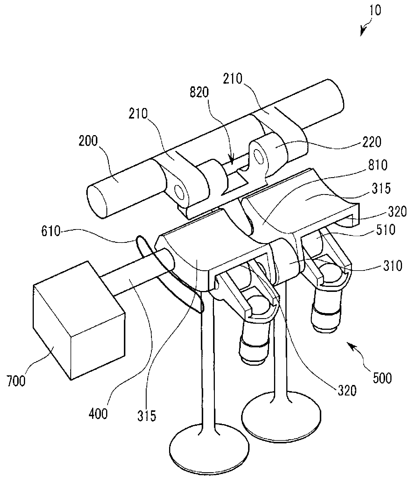
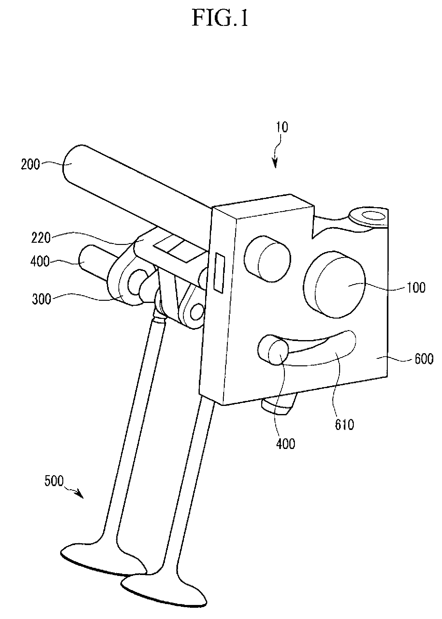
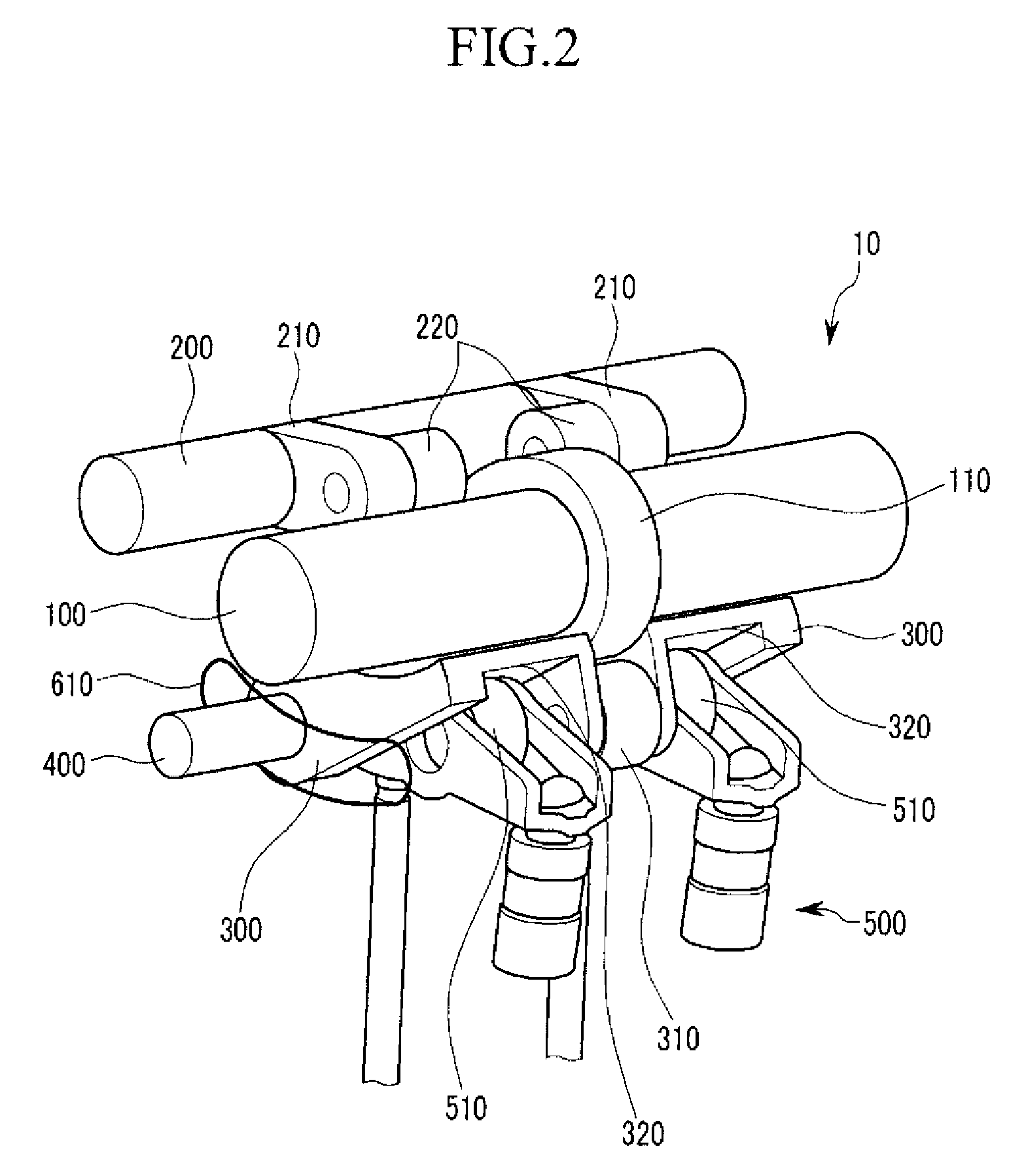
[0043]Referring to FIG. 1 to FIG. 3, a continuously variable valve lift apparatus 10 according to a first exemplary embodiment of the present invention includes an input cam 110 disposed to an input shaft 100, a first shaft 200 positioned in parallel with the input shaft 100, a first link 210 connected with the first shaft 200, and a second link 220 rotatably coupled to the first link 210.

[0044]An output cam 300 is rotatably coupled to the second link 220 and configured with a contact portion contacting the input cam 110.

[0045]A second shaft 400 is disposed to the output cam 300 in parallel with the input shaft 100.

[0046]At least one valve unit 500 is opened and closed by operation of the output cam 300.

[0047]Referring to FIG. 1, the first shaft 200 and the input shaft 100 are supported by a supporting portion 600, and a guiding slot 610 is forme...


PUM


Abstract

A continuous variable valve lift apparatus according to an exemplary embodiment of the present invention includes an input cam disposed to an input shaft, a first shaft in parallel with the input shaft, a first link connected with the first shaft, a second link rotatably connected to the first link, an output cam that is rotatably connected with the second link and configured with a contact portion contacting the input cam, a second shaft disposed to the output cam parallel with the input shaft, at least one valve unit that is opened and closed by the output cam, and a control part that controls a position of the second shaft.

Description

CROSS-REFERENCE TO RELATED APPLICATION[0001]This application claims priority to and the benefit of Korean Patent Application No. 10-2007-0131575 filed in the Korean Intellectual Property Office on Dec. 14, 2007, the entire contents of which are incorporated herein by reference.BACKGROUND OF THE INVENTION[0002](a) Field of the Invention[0003]The present invention relates to a continuous variable valve lift apparatus. More particularly the present invention relates to a continuous variable valve lift apparatus that can adjust a valve lift amount in response to an operational state of an engine.[0004](b) Description of the Related Art[0005]A typical combustion chamber of an automotive engine is provided with an intake valve for supplying an air / fuel mixture and an exhaust valve for expelling burned gas. The intake and exhaust valves are opened and closed by a valve lift apparatus connected to a crankshaft.[0006]A conventional valve lift apparatus has a fixed valve lift amount due to a ...

Claims


Application Information

Patent Timeline
Patent Type & Authority Applications(United States)
IPC IPC(8): F01L1/047
CPCF01L13/0063F01L1/053F01L1/14F01L1/18F01L1/255F01L13/00
Inventor KWAK, YOUNG HONGKWON, KIYOUNGKONG, JIN KOOKCHANG, KYOUNG JOON
Owner HYUNDAI MOTOR CO LTD
Why Eureka
Try Eureka