AI technical title is built by Patsnap AI team. It summarizes the technical point description of the patent document.
a ptychography and system technology, applied in the field of ptychography based system and method, can solve the problems of limited frame rate increase using ccd or cmos technology, complicated ultrahigh-speed cameras or microscopes,
Active Publication Date: 2022-05-31
TECHNION RES & DEV FOUND LTD
View PDF4 Cites 1 Cited by
Summary
Abstract
Description
Claims
Application Information
AI Technical Summary
This helps you quickly interpret patents by identifying the three key elements:
Problems solved by technology
Method used
Benefits of technology
Benefits of technology
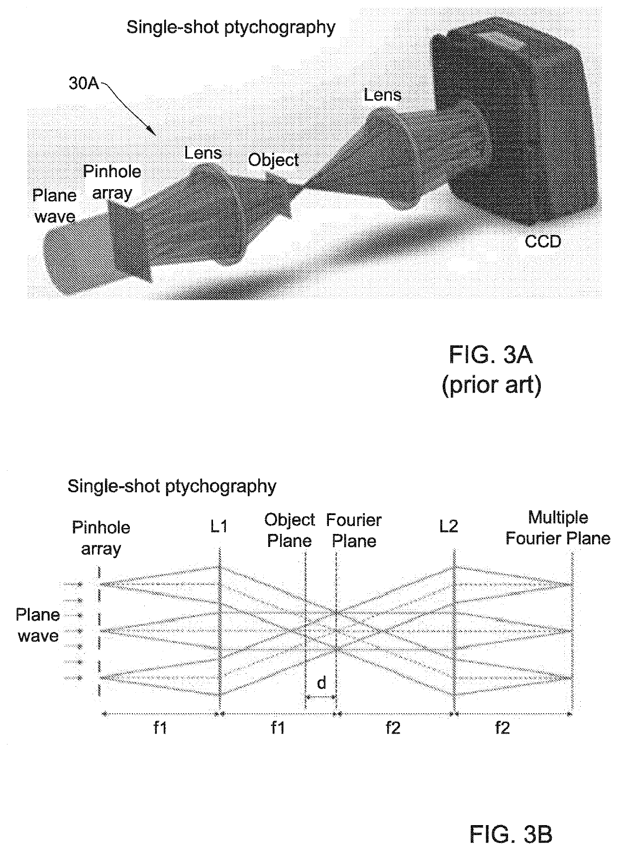
[0021]The present invention provides a novel ultrahigh-speed imaging approach that is based on ptychography. In ptychography, a complex-valued object is scanned in a stepwise fashion through a localized coherent illumination. In each scanning step, the far-field diffraction pattern of the object is measured, typically in a Fraunhofer plan. The set of diffraction patterns is used for reconstructing a complex transfer function describing the object. Critically, the illumination spot in each step overlaps substantially with neighboring spots. Thus, the recorded information is highly redundant, leading to several advantages of ptychography over ordinary coherent diffraction imaging including improved robustness to noise, no requirement for prior information (e.g. support) on the object, reconstructions of both the imaged sample and the probe beam simultaneously, and generally faster and more reliable reconstruction algorithms.
[0026]Thus, in some embodiments of the invention, the novel technique of the present invention utilizes ptychographical information multiplexing in single-shot ptychography that is illuminated by a burst of pulses. In this connection, it should be noted that such burst of pulses may be produced by a pulsed light source, or may alternatively be produced by a CW light source (e.g. laser) and a spatial light modulator (SLM). Generally speaking, the object illumination may be such that each exposure session includes a series of multiple temporal frames of the object resulting in a single intensity pattern recorded by the detection device, by either a single 2D pixel array or two or more such pixel arrays forming together a pixel matrix that records the intensity in a single exposure session. The inventors termed the technique of these embodiments as “Time-resolved Imaging by Multiplexed Ptychography (TIMP). In this technique, complex-valued multiple frames of the object are recovered from the image data measured using a single pixel-matrix exposure (by one or multiple CCDs, but in the single shot / exposure session) in a single-shot ptychography (SSP) system. The framerate and temporal resolution in TIMP are determined by an illumination device, and not the imaging system, making this method very flexible. It should be noted that the TIMP imaging system utilizes simple elements, hence it can be implemented across the electromagnetic spectrum (including extreme UV and x-rays), as well as with other waves.
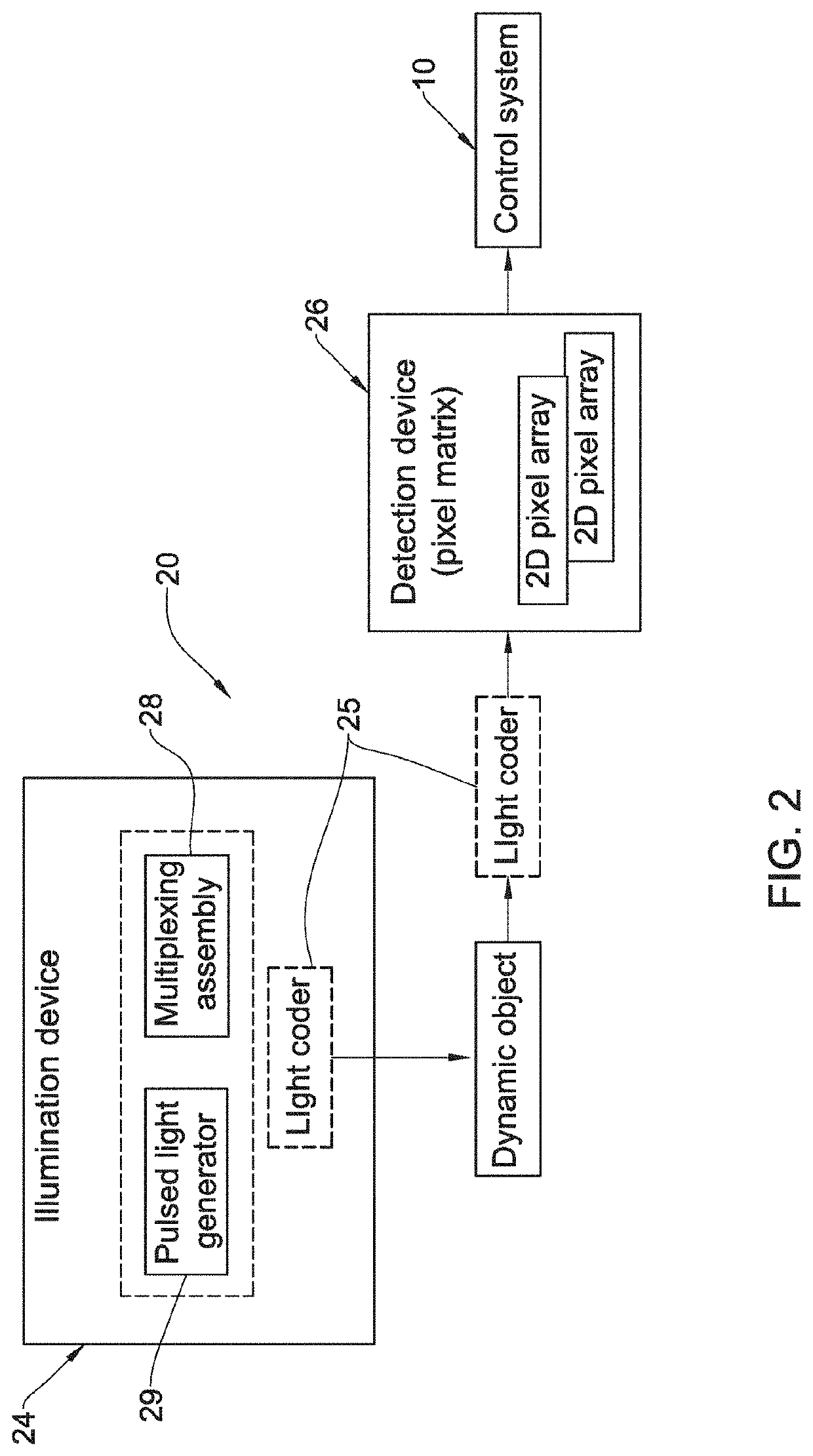
[0029]In some embodiments, the optical system comprises the light coding device configured and operable to produce the illuminating light having a predetermined time pattern thereby producing the light response in the form of corresponding temporal frames of the multiplexed light responses detected by the pixel matrix during the same exposure session, thereby providing time-resolved imaging of the multiplexed light responses of the object during the single exposure session, thereby enabling imaging of a dynamic object.
Problems solved by technology
This is because imaging of non-repetitive ultrafast dynamical objects requires complicated ultrahigh-speed cameras or microscopes (as compared to the known pump-probe techniques employed for exploring repetitive ultrafast events).
Further increase in the frame rate using CCD or CMOS technology is limited by their on-chip storage and electronic readout speed.
Method used
Image
Click on the blue label to locate the original text in one second.
Reading with bidirectional positioning of images and text.
Examples
Embodiment Construction
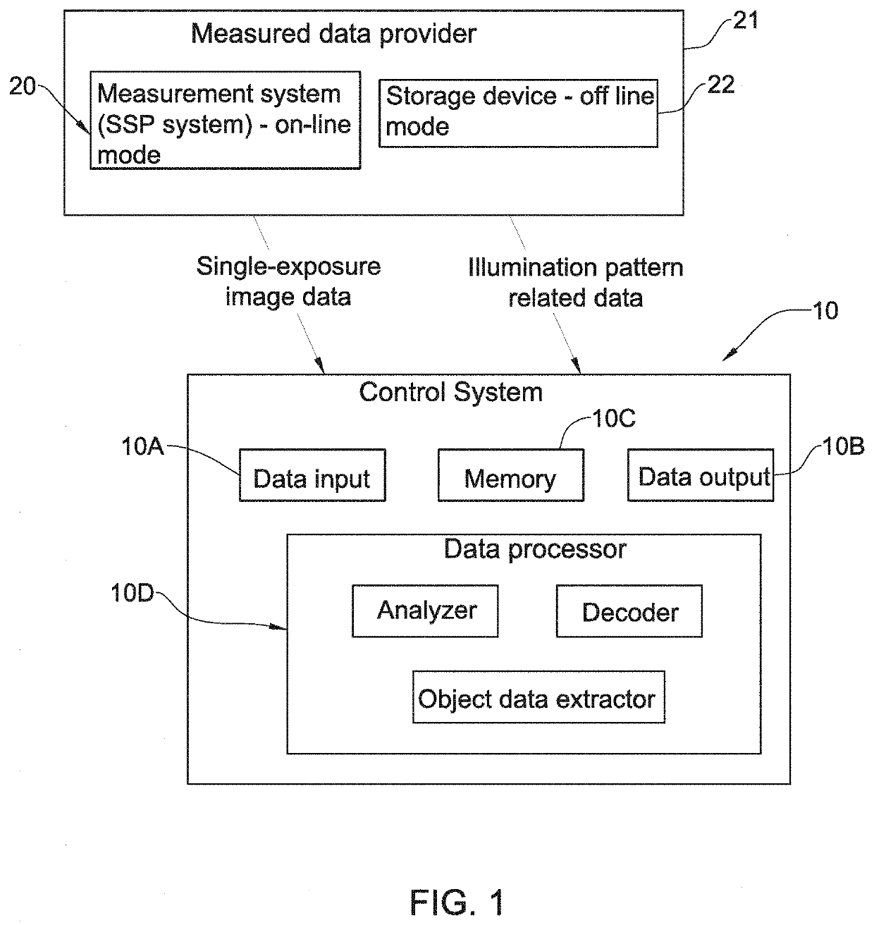
[0069]Reference is made to FIG. 1, which illustrates, by way of a block diagram, a control system 10 configured and operable according to the invention for receiving and processing image data obtained by an SSP imaging system 20 of the invention utilizing the concept of TIMP technique. The control system 10 is typically a computer system comprising such main hardware / software utilities as data input 10A, data output 10B, memory 10C, and data processor 10D. It should be understood that image data to be processed by the control system 10 is received from / provided by a measured data provider 21, which may be the SSP system 20 itself (on-line object reconstruction mode) and / or a storage device 22 (off-line operational mode), which may be either a separate device or a part of the SSP system. The computer system 10 may thus be configured for data communication (e.g. via a communication network) with the measured data provider 30.
[0070]The data processor 10D is configured and operable to p...
PUM
Abstract
A ptychography system is presented for imaging an object located in an object plane. The ptychography system comprises an optical system, and a detection device. The optical system comprises a single shot ptychography arrangement configured and operable to create light response patterns from the object in the object plane on a pixel matrix of the detection device during the same exposure session of the detection device, wherein the optical system further comprises at least one light coding device configured and operable to apply at least one predetermined coding function to at least one of illuminating light and the light response of the object being collected, and said detection device is configured and operable with a predetermined duration of the exposure session during which the pixel matrix detects the collected light, such that image data indicative of the detected light during a single exposure session is in the form of a coded light response of the object being illuminated.
Description
TECHNOLOGICAL FIELD[0001]The present invention is in the field of imaging techniques, and is specifically relevant for imaging of non-repetitive ultrafast dynamical objects.BACKGROUND ART[0002]References considered to be relevant as background to the presently disclosed subject matter are listed below:[0003]1. K. Nakagawa, A. Iwasaki, Y. Oishi, R. Horisaki, A. Tsukamoto, A. Nakamura, K. Hirosawa, H. Liao, T. Ushida, K. Goda, F. Kannari, and I. Sakuma, “Sequentially timed all-optical mapping photography (STAMP),” Nat. Photonics 8(9), 695-700 (2014).[0004]2. L. Gao, J. Liang, C. Li, and L. V. Wang, “Single-shot compressed ultrafast photography at one hundred billion frames per second,” Nature 516(7529), 74-77 (2014).[0005]3.10. X. Chen, J. Wang, M. Versluis, N. de Jong, and F. S. Villanueva, “Ultra-fast bright field and fluorescence imaging of the dynamics of micrometer-sized objects,” Rev. Sci. Instrum. 84(6), 063701 (2013).[0006]4. K. Goda, K. K. Tsia, and B. Jalali, “Amplified disp...
Claims
Application Information
Patent Timeline
Application Date:The date an application was filed.
Publication Date:The date a patent or application was officially published.
First Publication Date:The earliest publication date of a patent with the same application number.
Issue Date:Publication date of the patent grant document.
PCT Entry Date:The Entry date of PCT National Phase.
Estimated Expiry Date:The statutory expiry date of a patent right according to the Patent Law, and it is the longest term of protection that the patent right can achieve without the termination of the patent right due to other reasons(Term extension factor has been taken into account ).
Invalid Date:Actual expiry date is based on effective date or publication date of legal transaction data of invalid patent.

