Method for forming the image in millimetre and sub-millimetre wave band (variants), system for forming the image in millimetre and sub-millimeter wave band (variants), diffuser light (variants) and transceiver (variants)

Inactive Publication Date: 2006-12-07
ASTRAZENECA AB
View PDF3 Cites 118 Cited by
  • Summary
  • Abstract
  • Description
  • Claims
  • Application Information

AI Technical Summary

Benefits of technology

[0018] Such a extended set of partial images each of which exhibits various sets of values of physical features allow to perform enhance identification of objects and noise and other disturbances in the resultant image. Having an access to different portions of the partial images, distinctly containing the object and the disturbance, it is possible to weighted combined of the portions with according to chosen criteria, for example, to minimize a level of the disturbance of quality of the resultant comb

Problems solved by technology

Possibilities of the majority of the methods are limited only by binary (yes/no) detection of the presence of metallic items, without revealing any details, features or even information about item location.
Such devices cannot be used for stealthy, efficient and real time contraband detection with a low level of false alarm.
Such conventional detection systems are not effective because they are not sensitive to plastic and ceramic weapons.
It Is known that passive radiometric MMW/SMMW imaging systems are inherently ineffective indoor, wherein the majority of inspection procedures are performed, This ineffectiveness is conditioned by the low level of radiometric brightness temperature contrast in illumination of the objects being located indoor in comparison with the items located outdoor, wherein the items are illuminated by means of “cold” sky, brightness temperature of which is about T=70 K, and by means of “warm” surface of the Earth with the brightness temperature near T=300 K.
Since state-of-the-art real time radiometric imaging systems have a temperature sensitivity of about 1 K, radiometric images generated by such systems exhibit low visible quality with high level of noises caused by said low contrast.
In any case non-observance of this condition results in the fact that the images being

Method used


Image

  • Method for forming the image in millimetre and sub-millimetre wave band (variants), system for forming the image in millimetre and sub-millimeter wave band (variants), diffuser light (variants) and transceiver (variants)
  • Method for forming the image in millimetre and sub-millimetre wave band (variants), system for forming the image in millimetre and sub-millimeter wave band (variants), diffuser light (variants) and transceiver (variants)
  • Method for forming the image in millimetre and sub-millimetre wave band (variants), system for forming the image in millimetre and sub-millimeter wave band (variants), diffuser light (variants) and transceiver (variants)

Examples


Embodiment Construction

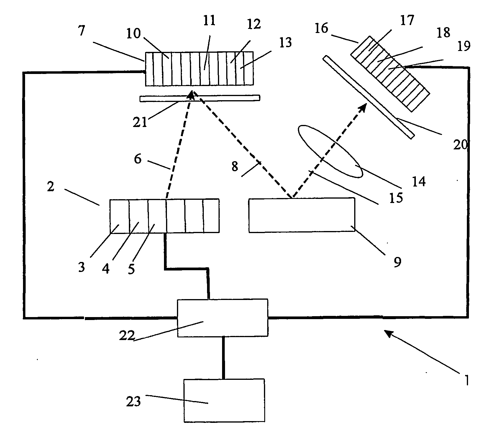
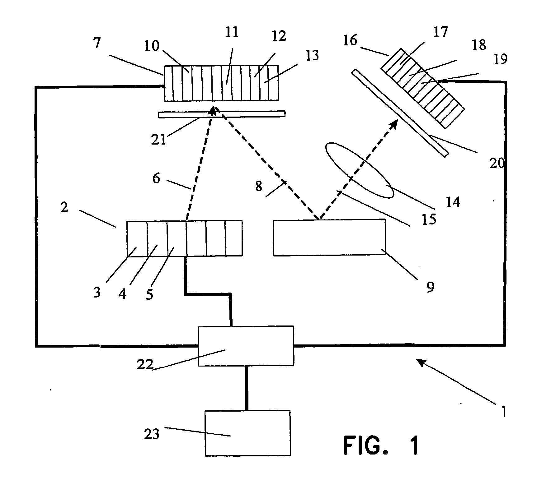
[0093] In accordance with the present invention the first method for millimeter and sub-millimeter wave imaging, consists in the steps of forming a composite radiation in the millimeter and sub-millimeter range of waves, consisting of separate partial radiations, differing from one another by values of their physical features, directing the formed radiations forward to the observed object, receiving the? radiation, being scattered with the observed object, from a radiation-focusing element, transforming the received radiation in electrical signals and in forming a visually accepted image of the observed object in accordance with the given electrical signals. In accordance with this method, each separate partial radiation is additionally encoded by means of its modulation, which differs from a modulation of other partial radiations, the partial radiations are directed to a diffuser for decreasing their spatial coherence and / or their dispersing by means of different portions of the di...


PUM


Abstract

The invention relates to the field of computer diagnostics. The method consists in the steps of forming radiation forming in this wave range, consisting of separate partial radiations, which are different from each other by values of their physical features, directing of the formed radiations into a side of the observed object, receiving a radiation, dispersed from the observed object, through a focusing element, transforming of the received radiation in electrical signals and forming a synthesized enhance image of the observed object by combining said given electrical signals. Besides, each separate partial radiation is additionally distinctly encoded for example by means of its modulation, which differs from a modulation of other partial radiations, the partial radiations are directed to a diffuser for decreasing their spatial coherence and/or their dispersing by means of different portions of the diffuser in order to create an additional distinctly encoded partial radiations with an additional modulation, corresponding to an angle of impingement onto the observed object. After reflecting of the radiation from the observed object the step of focusing of this radiation to a receiving device is realized, which accomplishes a transforming of set of partial radiations in a corresponding array set of electrical signals, there is realized the step of decoding of partial electrical signals, corresponding to said partial radiations, from each of said electrical signals of said array set there are formed partial images from array sets with various partial electrical signals and then an combination of the partial images or their portions is realized in order to form enhanced resultant image of the object.

Description

FIELD OF THE INVENTION [0001] The present invention relates to real time computer diagnostics, in particular, to systems and methods for remote detection of weapons, explosives and drugs, concealed on person body beneath its clothes or in luggage, which are based on the quasi-optical imaging of such items, in particular in the range of millimeter and submillimeter waves. BACKGROUND OF THE INVENTION [0002] Detection of concealed objects based on formation of their images, millimeter and submillimeter wave (hereinafter referred to as “MMW / SMMW”) radiation has advantages due to high level of its permeability through the atmosphere under foul weather conditions and through various fabrics, plastic, ceramic, wooden materials and other media being opaque in the visible range. Owing to a relatively short wavelength of the MMW / SMMW radiation there are opportunities of designing of imaging systems exhibiting quite high spatial resolution in formed images. Such imaging systems may be effectiv...

Claims


Application Information

Patent Timeline
IPC IPC(8): H01L25/00G01T1/00G01S13/00G01J5/02G01J1/00G01S7/02G01S7/41G01S7/42G01S13/87G01S13/88G01S13/89G01V3/12G01V8/00
CPCG01S7/024G01S7/41G01S7/411G01S7/414G01S13/89G01S13/87G01S13/88G01S13/887G01S7/42
Inventor VOLKOV, LEONID VICTOROVICHVORONKO, ALEXANDR IVANOVICH
Owner ASTRAZENECA AB
Why Eureka
Try Eureka