Noise reduction system with remote noise detector

Active Publication Date: 2013-10-03
MEDIATEK INC
View PDF8 Cites 93 Cited by
  • Summary
  • Abstract
  • Description
  • Claims
  • Application Information

AI Technical Summary

Benefits of technology

[0003]It is an object of the present invention to provide an enhanced noise reduction system which

Problems solved by technology

Current single-microphone speech enhancement techniques suffer from poor performance in non-stationary noise conditions, and

Method used


Image

  • Noise reduction system with remote noise detector
  • Noise reduction system with remote noise detector
  • Noise reduction system with remote noise detector

Examples


Embodiment Construction

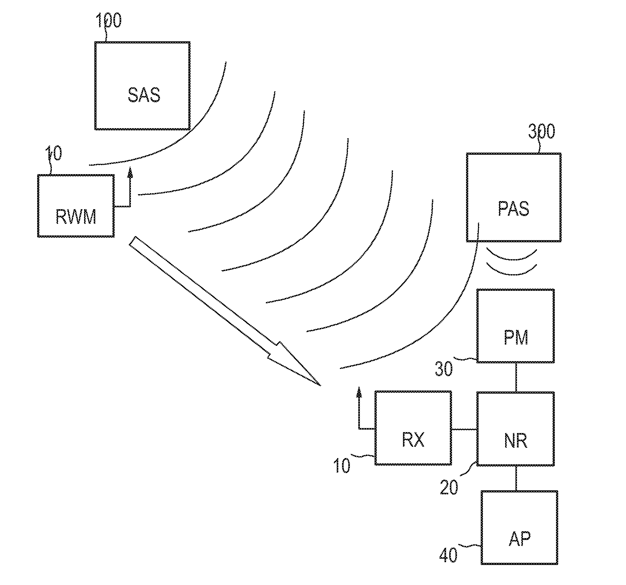
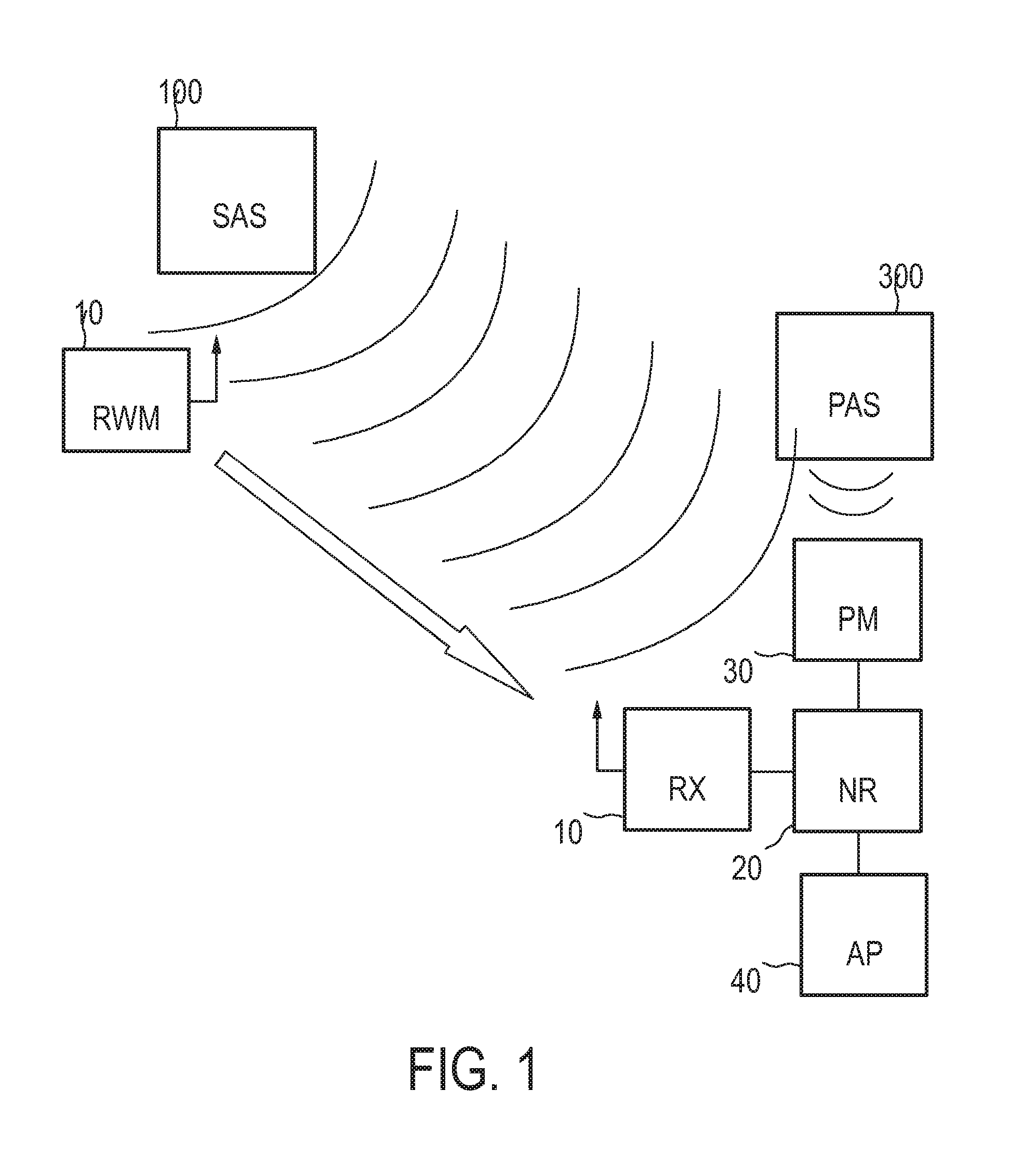
[0023]FIG. 1 shows a noise reduction system according to an embodiment where a primary acoustic source (PAS) 300, such as a user's voice for a VoIP call or any other source of a desired acoustic signal, is received via a primary microphone (PM) 30 or any other detector for acoustic or audio signals. The detected audio signal is supplied to a noise reduction unit (NR) 20 adapted to cancel or suppress noise and / or interference added during the signal detection process. More specifically, the noise reduction unit or processor 20 is adapted to determine or estimate any noise and / or interference added to the desired signal by other remote secondary acoustic sources (SAS), such as the secondary acoustic source 100 depicted in FIG. 1. The secondary acoustic source 100 may be a television (TV) device, a music player or any other source of background noise or interference which influences the desired signal to be detected by the primary microphone 30. Interference and / or noise determination ...


PUM


Abstract

Noise reduction system with remote noise detector The present invention relates to a noise reduction system with at least one remote noise detector placed close to at least one noise source, which transmits relevant information to a primary device where it is used for noise reduction. Thereby, acoustic signal enhancement can be achieved via the at least one remote noise detector in that a noise estimate is transmitted to controller for noise reduction in the signal obtained from a primary source.

Description

FIELD OF THE INVENTION[0001]The invention relates to a noise reduction apparatus, method and system for reducing background noise and / or interference during reception of an acoustic signal.BACKGROUND OF THE INVENTION[0002]Enhancement of speech corrupted by background noise and interference remains a challenging problem, especially for highly varying interfering audio or acoustic signals such as music. This is a relevant problem in several application domains, e.g., mobile telephony, hands-free communication, hearing aids, etc. As voice over Internet Protocol (VoIP) communication becomes increasingly common in living rooms, a new application scenario emerges, where one person in a home is involved in a VoIP call, e.g., on a personal computer (PC), while another person is watching television (TV) or listening to music, in the same room. As VoIP conversations tend to be long, these scenarios demand increasing attention. The challenge is to transmit only the voice of the talker while su...

Claims


Application Information

Patent Timeline
IPC IPC(8): G10L21/0208G10L21/02G10L21/0216
CPCG10L2021/02165G10L21/0208
Inventor SRINIVASAN, SRIRAM
Owner MEDIATEK INC
Why Eureka
Try Eureka