
System for restarting internal combustion engine when engine restart condition is met

a technology for internal combustion engines and ring gears, which is applied in the direction of engine starters, machines/engines, instruments, etc., can solve the problems of non-smooth engagement of pinions with ring gears and increase noise, and achieve the effect of reliably engaging pinions, reducing noise, and reducing nois

Active Publication Date: 2011-03-10
DENSO CORP
View PDF23 Cites 114 Cited by
  • Summary
  • Abstract
  • Description
  • Claims
  • Application Information

AI Technical Summary

Benefits of technology

[0011]Specifically, the present invention aims at providing systems for restarting an internal combustion engine; these systems are designed to carry out engagement of a pinion of a starter with a ring gear at a proper timing that can reduce noise due to the engagement of the pinion with the ring gear and / or make smooth the engagement of the pinion with the ring gear. This design can properly crank the internal combustion engine.
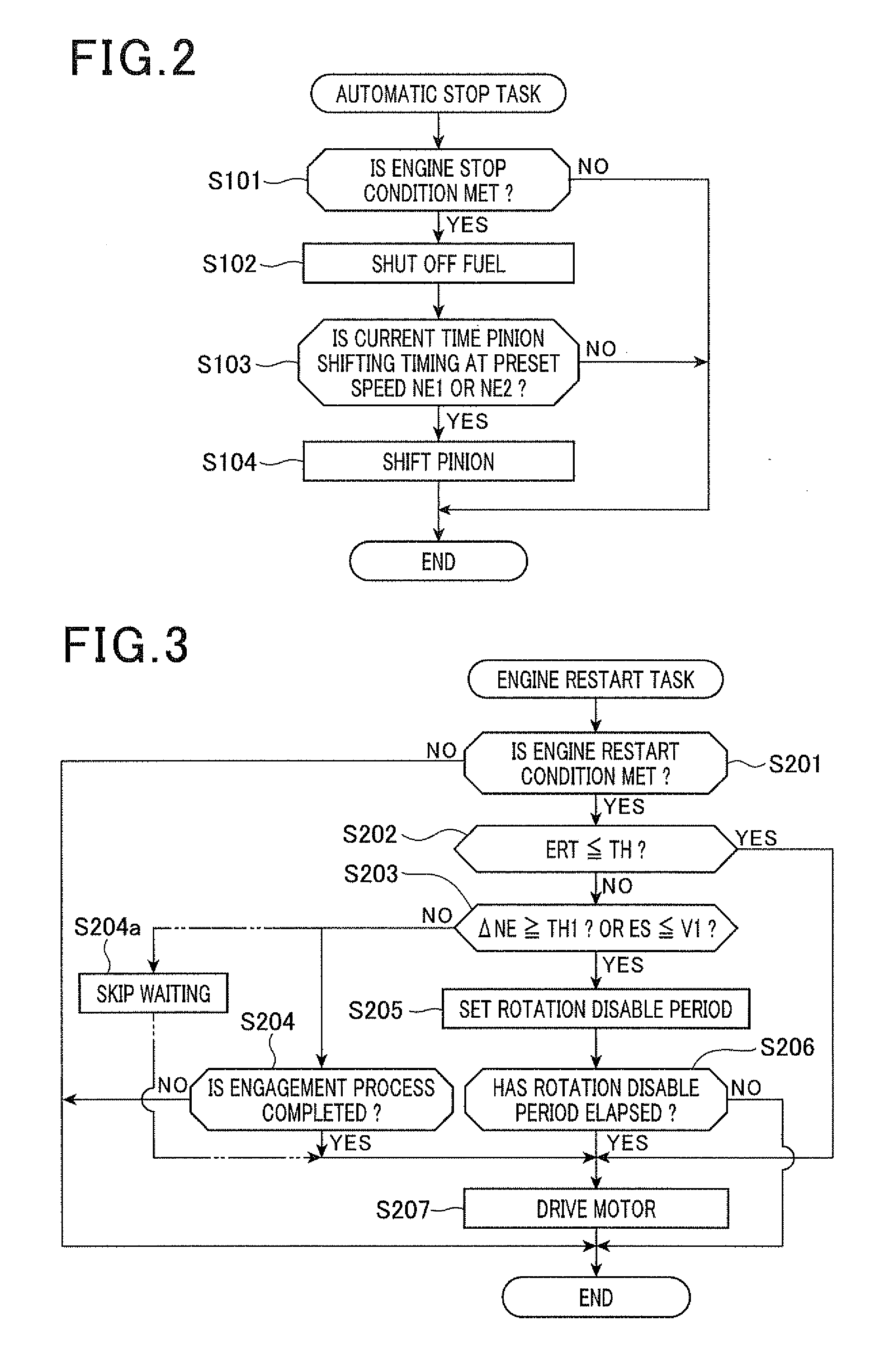
[0013]In normal idle reduction control, during an internal combustion engine (engine) coasting, a pinion of a starter is previously shifted to be engaged with a ring gear coupled to an output shaft of the engine before an engine restart condition is met. In the starter, the pinion is located away from the ring gear except for the process of normal start or restart of the engine so that it takes a certain amount of time until the engagement of the pinion with the ring gear has been completed since the start of the shift of the pinion to the ring gear. In addition, when an engine restart condition is met during the interval between the start of the shift of the pinion to the ring gear and the complete of the engagement of the pinion with the ring gear, the rotating pinion may be engaged with the ring gear just before it stops rotating, resulting in an increase in noise due to the strike and / or the friction between the pinion and the ring gear during the engagement of the pinion with the ring gear. This case also may make non-smooth the engagement of the pinion with the ring gear.
[0015]Thus, the one aspect of the present invention is configured to delay the start timing of rotation of the pinion after the pinion is completely or at least partly engaged with the ring gear. This makes it possible to, even if an engine restart condition is met during a process of the engagement of the pinion with the ring gear, reliably engage the pinion with the ring gear while reducing noise due to the engagement of the pinion with the ring gear. Accordingly, this one aspect of the present invention properly engages the pinion with the ring gear, thus properly cranking the internal combustion engine.
[0016]The one aspect of the present invention is capable of delaying the start timing of rotation of the pinion after the pinion is in abutment with the ring gear. Even before the completion of engagement of the pinion with the ring gear, when the pinion is in abutment with the ring gear, the engagement of the pinion with the ring gear is carried out immediately after the abutment of the pinion with the ring gear. For this reason, the one aspect of the present invention makes it possible to reliably engage the pinion with the ring gear and reduce noise due to the engagement of the pinion with the ring gear.

Problems solved by technology

The inventors have discovered that there is a problem in the starter drive control disclosed in these patent Publications.
In this case, the rotating pinion may be engaged with the ring gear just before it stops rotating, resulting in an increase in noise due to the strike and / or the friction between the pinion and the ring gear during the engagement of the pinion with the ring gear.
This case also may make non-smooth the engagement of the pinion with the ring gear.

Method used


Image

  • System for restarting internal combustion engine when engine restart condition is met
  • System for restarting internal combustion engine when engine restart condition is met
  • System for restarting internal combustion engine when engine restart condition is met

Examples


first embodiment

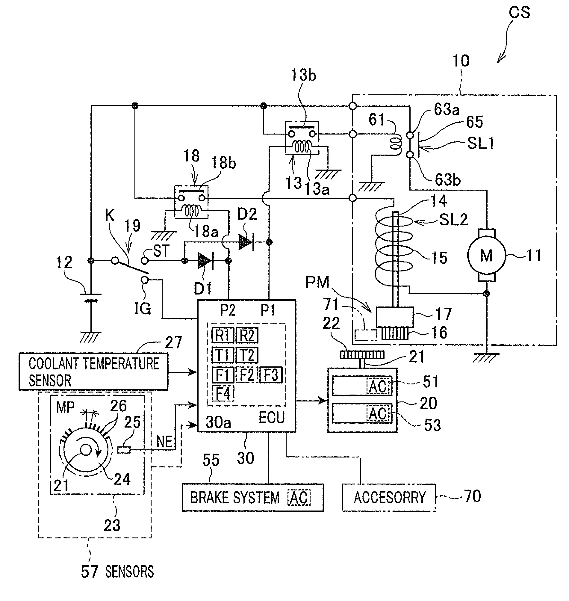
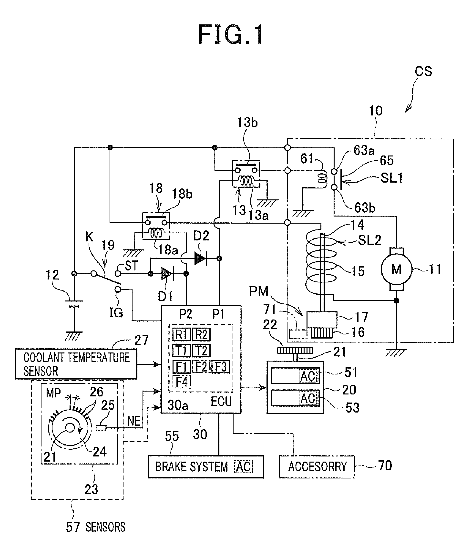
[0033]In the first embodiment, the present invention is applied to an engine starting system designed as a part of an engine control system CS installed in a motor vehicle. The engine control system CS is comprised of an electronic control unit (ECU) 30 as a central device thereof, and is operative to control the quantity of fuel to be sprayed and the timing of ignition, and carry out a task of automatically stopping an internal combustion engine (referred to simply as engine) 20 and a task of restarting the engine 20. An example of the overall structure of the engine control system CS is illustrated in FIG. 1.

[0034]Referring to FIG. 1, the engine 20 has a crankshaft 21, as an output shaft thereof, with one end to which a ring gear 22 is directly or indirectly coupled.

[0035]The engine 20 works to compress air-fuel mixture or air by a moving piston within each cylinder, and burn the compressed air-fuel mixture or the mixture of the compressed air and fuel within each cylinder to chan...

second embodiment

[0191]An engine control system according to the second embodiment of the present invention will be described hereinafter with reference to FIGS. 7A to 10.

[0192]The structure and / or functions of the engine control system according to the second embodiment are different from the engine control system CS by the following points. So, the different points will be mainly described hereinafter.

[0193]The engine control system CS according to the first embodiment is designed to wait for the completion of the engagement of the pinion 16 with the ring gear 22 after the start of the shift of the pinion 16 to the ring gear 22, and thereafter drive the motor 11.

[0194]In contrast, the engine control system according to the second embodiment is configured to, after the start of the shift of the pinion 16 to the ring gear 22, drive the motor 11 at the moment when the pinion 16 is in abutment with (contact with) the ring gear 22. When the pinion 16 is in abutment with the ring gear 22, the pinion 16 ...


PUM


Abstract

In a system, a pinion shift unit starts shift of a pinion to a ring gear for engagement therebetween during an internal combustion engine coasting in a forward direction after an automatic stop of the internal combustion engine. An engagement determining unit determines whether the pinion and the ring gear have any one of first and second positional relationships therebetween. The first positional relationship represents that the pinion is at least partly engaged with the ring gear. The second positional relationship represents that the pinion is in abutment with the ring gear. When an engine restart condition is met before it is determined that the pinion and the ring gear have any one of first and second positional relationships therebetween after the start of the shift of the pinion to the ring gear, a rotation adjusting unit adjusts a start timing of rotation of the pinion.

Description

[0001]This application is based on Japanese Patent Applications 2009-204536 and 2010-173608 filed on Sep. 4, 2009 and Aug. 2, 2010, respectively. This application claims the benefit of priority from the Japanese Patent Applications, so that the descriptions of which are all incorporated herein by reference.FIELD OF THE INVENTION[0002]The present invention relates to systems for restarting internal combustion engines when at least one of predetermined engine restart conditions is met.BACKGROUND OF THE INVENTION[0003]Engine stop-and-start systems, such as idle reduction control systems, have been recently developed. Such engine stop-and-start systems are designed to automatically stop an internal combustion engine of a vehicle in response to detecting a driver's engine stop operation, such as the operation of a brake pedal. These engine stop-and-start systems are also designed to restart the internal combustion engine in response to detecting a driver's operation to start the vehicle,...

Claims


Application Information

Patent Timeline
IPC IPC(8): F02N11/08G06F19/00
CPCF02N11/0855F02N2200/048F02N2200/022F02N11/0844
Inventor NOTANI, HIDEYA
Owner DENSO CORP
Learn More