Heat Pump System in Vehicle

Active Publication Date: 2015-10-15
HYUNDAI MOTOR CO LTD
View PDF51 Cites 0 Cited by
  • Summary
  • Abstract
  • Description
  • Claims
  • Application Information

AI Technical Summary

Benefits of technology

[0030]Thus, the heat pump system in a vehicle in accordance with various embodiments of the present invention has advantages of embodying the cooling, heating, and dehumidifying modes to simplify elements thereof compared to the related art, as well as to minimize a number of valves mounted to the pipelines to save a production cost and simplify a package by makin

Problems solved by technology

Consequently, a problem is caused, in that an entire system package increases due to addition of an element and complicated pipe layout, and a production cost increases.
Moreover, if the heat exchanger is provided to the cabin, mounting

Method used


Image

  • Heat Pump System in Vehicle
  • Heat Pump System in Vehicle
  • Heat Pump System in Vehicle

Examples


Embodiment Construction

[0038]Reference will now be made in detail to various embodiments of the present invention(s), examples of which are illustrated in the accompanying drawings and described below. While the invention(s) will be described in conjunction with exemplary embodiments, it will be understood that the present description is not intended to limit the invention(s) to those exemplary embodiments. On the contrary, the invention(s) is / are intended to cover not only the exemplary embodiments, but also various alternatives, modifications, equivalents and other embodiments, which may be included within the spirit and scope of the invention as defined by the appended claims.

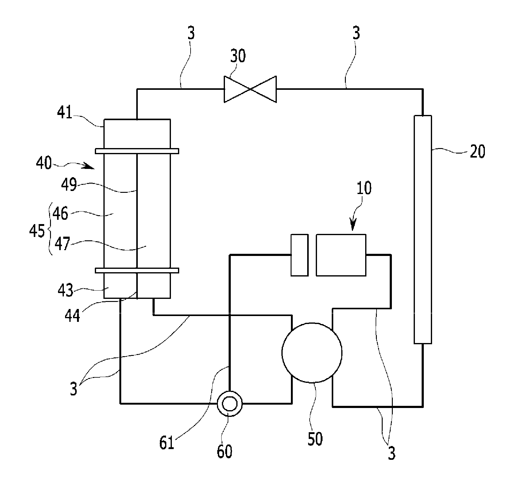
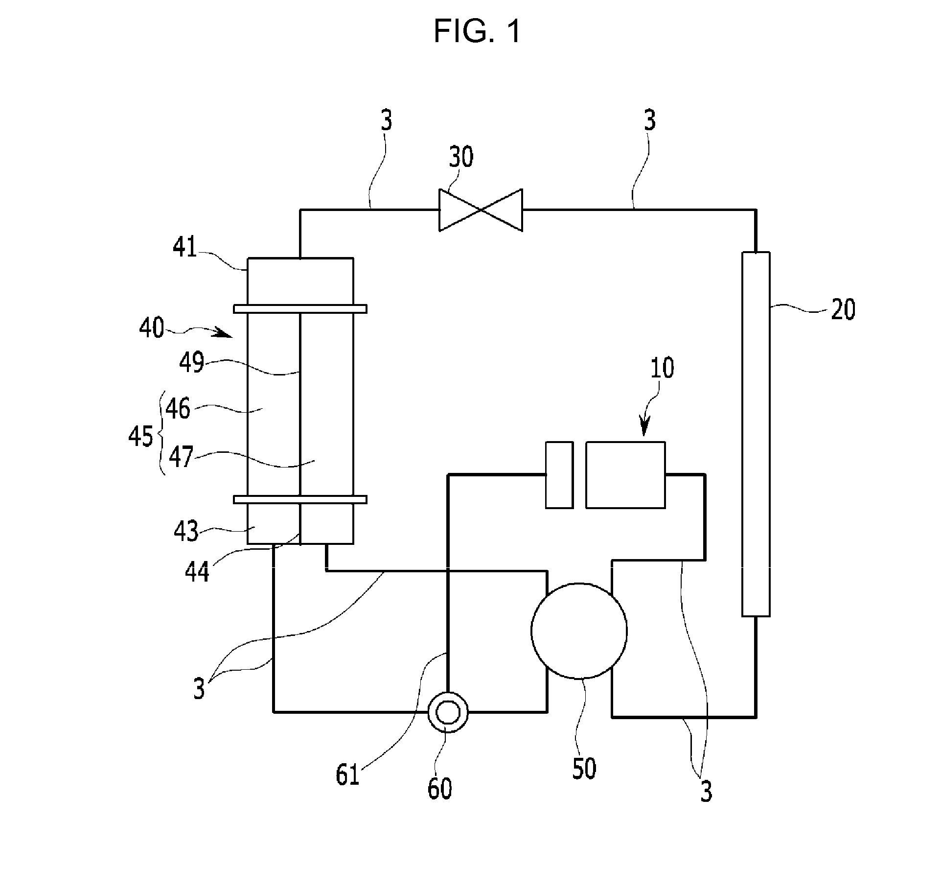
[0039]FIG. 1 illustrates a block diagram of a heat pump system in a vehicle in accordance with various embodiments of the present invention.

[0040]Referring to FIG. 1, the heat pump system in a vehicle is connected with refrigerant line 3 through which refrigerant flows for controlling cooling / heating a cabin of a vehicle, and incl...


PUM


Abstract

A heat pump system in a vehicle connected with a refrigerant line through which refrigerant flows for controlling cooling/heating of a cabin of the vehicle, including a compressor for compressing refrigerant, an outdoor heat exchanger for condensing high temperature and high pressure refrigerant compressed at the compressor, and an expansion valve for expanding the refrigerant compressed thus, may include an indoor heat exchanger arranged between the compressor and the expansion valve connected to one another with the refrigerant line, and having a partitioned inside to form individual flow passages, and a first valve connected to the compressor, the outdoor heat exchanger and the indoor heat exchanger with the refrigerant line for changing a direction of a refrigerant flow according to cooling, heating, and dehumidifying modes of the vehicle to control the refrigerant flow along the refrigerant line.

Description

CROSS-REFERENCE TO RELATED APPLICATION[0001]The present application claims priority to Korean Patent Application No. 10-2014-0044237 filed in Apr. 14, 2014, the entire contents of which is incorporated herein for all purposes by this reference.BACKGROUND OF THE INVENTION[0002]1. Field of the Invention[0003]The present invention relates to a heat pump system in a vehicle. More particularly, the present invention relates to a heat pump system in a vehicle, which embodies heating, cooling and dehumidifying functions with one heat exchanger which also performs a function of an evaporator.[0004]2. Description of Related Art[0005]In general, an air conditioner in the vehicle includes an air conditioner module for cooling and heating a cabin in the vehicle.[0006]The air conditioner module is configured to cool the cabin with a heat exchange medium owing to heat exchange of the heat exchange medium with the evaporator, or to heat the cabin with cooling water by introducing the cooling water...

Claims


Application Information

Patent Timeline
IPC IPC(8): F25B13/00B60H1/32
CPCB60H1/3204F25B13/00B60H1/00907B60H2001/00935B60H2001/00942F25B2313/02323F25B2313/02331F25B2313/02333B60H1/323
Inventor YOO, JINYOUNGLEE, KILWOO
Owner HYUNDAI MOTOR CO LTD
Why Eureka
Try Eureka