Device and method for reducing switching losses in power transistors

Active Publication Date: 2017-04-20
ROBERT BOSCH GMBH
View PDF0 Cites 0 Cited by
  • Summary
  • Abstract
  • Description
  • Claims
  • Application Information

AI Technical Summary

Benefits of technology

[0013]The advantage here is that

Problems solved by technology

This results in high power losses.
The disadvantage here is that the working range of the step-down converter is limited by the serial coil present in the main path of the load current.
If the step-down converter leaves the optimal working point, de-energization is no longer possible, and the efficiency of the power transistor decreases consider

Method used


Image

  • Device and method for reducing switching losses in power transistors
  • Device and method for reducing switching losses in power transistors
  • Device and method for reducing switching losses in power transistors

Examples


Embodiment Construction

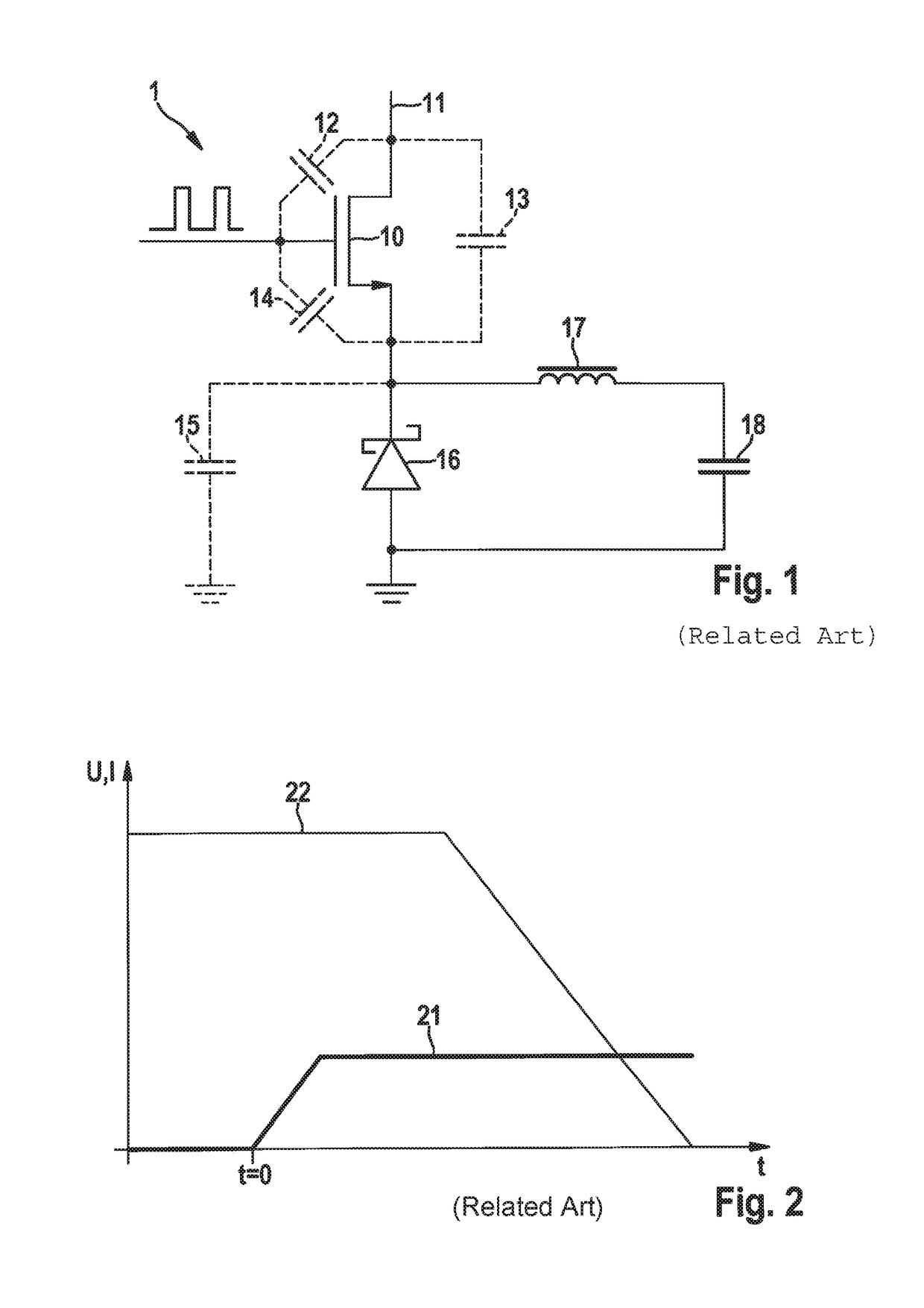
[0021]FIG. 1 shows an output stage 1 of a step-down converter from the related art. The output stage includes a power transistor 10. Power transistor 10 is connected on the drain side to a supply voltage 11. FIG. 1 furthermore shows coil 17 and capacitor 18 of the output filter as components. A Schottky diode 16 is provided in parallel to the output filter. The parasitic capacitances present during operation of the output stage are dotted in FIG. 1. Every time the power transistor is switched on, which acts as a power switch, the charge of all parasitic capacitances of the output stage must be resistively reversed. The charges of drain-source capacitance 13 and node capacitance 15 are reversed with the aid of an input resistance of power transistor 10 and cause high power losses of the output stage.

[0022]FIG. 2 shows the associated voltage and current curves when the power transistor is being switched on. When the power transistor is being switched on (t=0), current 21 rises drastic...


PUM


Abstract

A device including a first and second monitoring unit, the first monitoring unit detecting a first voltage potential and the second monitoring unit detecting a second voltage potential, the monitoring units comparing the first voltage potential and the second voltage potential to the value of the supply voltage and activate a control unit as a function of the comparisons, the control unit determining a switching point in time of a second power transistor, and an arrangement being present which generates current when the second power transistor is being switched on, the current changing the first voltage potential, and the control unit activates a first power transistor when the first voltage potential has the same value as the supply voltage, so that the first power transistor is de-energized.

Description

BACKGROUND INFORMATION[0001]The present invention relates to a device and to a method for reducing switching losses in power transistors. Every time a power transistor is switched, which acts as a power switch, for example, the charge of the parasitic capacitances of the output stage must be resistively reversed. This results in high power losses.[0002]Conventionally, a step-down converter may be configured with an oscillating circuit made up of a capacitor, which is connected in parallel between the drain and the source of the power transistor, and a coil, which is connected in series to the power transistor. With the aid of the oscillating circuit, the power transistor may be de-energized. The disadvantage here is that the working range of the step-down converter is limited by the serial coil present in the main path of the load current. If the step-down converter leaves the optimal working point, de-energization is no longer possible, and the efficiency of the power transistor de...

Claims


Application Information

Patent Timeline
IPC IPC(8): H02M1/088H02M3/158
CPCH02M1/088H02M2001/0054H02M3/158H03K17/133H03K17/166H03K2217/0036H03K2217/009Y02B70/10H02M1/0054
Inventor FUNK, TOBIASWITTMANN, JUERGENWICHT, BERNHARD
Owner ROBERT BOSCH GMBH
Why Eureka
Try Eureka