Optical guide including nanoparticles and manufacturing method for a preform intended to be shaped into such an optical guide

a technology of optical guides and nanoparticles, which is applied in the field of optical guides, can solve the problems of not allowing the incorporation of these elements in a satisfactory manner, requiring complicated and costly fibre production techniques, and requiring complex and costly production techniques. , to achieve the effect of easy welding of standard fibres

Inactive Publication Date: 2009-05-07
ALCATEL LUCENT SAS
View PDF2 Cites 36 Cited by
  • Summary
  • Abstract
  • Description
  • Claims
  • Application Information

AI Technical Summary

Benefits of technology

[0012]The present invention includes the observation that there exists a need for a method for manufacturing amplifying fibres that makes it possible to insert enhancement elements in the vicinity of the doping element in order to maintain physical properties closes to those of a standard silica fibre, and thereby to make it easier to weld the standard fibre to the amplifying fibre manufactured in this manner.

Problems solved by technology

This method has the disadvantage of not allowing these elements to be incorporated in a satisfactory manner into the preform prior to the manufacture of a fibre when said manufacturing uses a method called MCVD, for Modified Chemical Vapour Deposition.
Indeed, the MCVD introduces high temperatures, which are incompatible with the high volatility of numerous elements and / or with the low stability of compounds created using these elements.
However, the MOG method uses traditional glassmaking, mixing components in a crucible and exposing them to a high-temperature heat treatment that particularly has the disadvantage of requiring complicated and costly fibre production techniques.
Furthermore, the optical fibres produced using the MOG method have an optical signal attenuation rate higher than the attenuation rate for a fibre produced using the MCVD method, owing to the impurities introduced by crucible synthesis, and welding problems in relation to transmission fibres which are manufactured with the MCVD method.

Method used


Image

  • Optical guide including nanoparticles and manufacturing method for a preform intended to be shaped into such an optical guide
  • Optical guide including nanoparticles and manufacturing method for a preform intended to be shaped into such an optical guide
  • Optical guide including nanoparticles and manufacturing method for a preform intended to be shaped into such an optical guide

Examples


Embodiment Construction

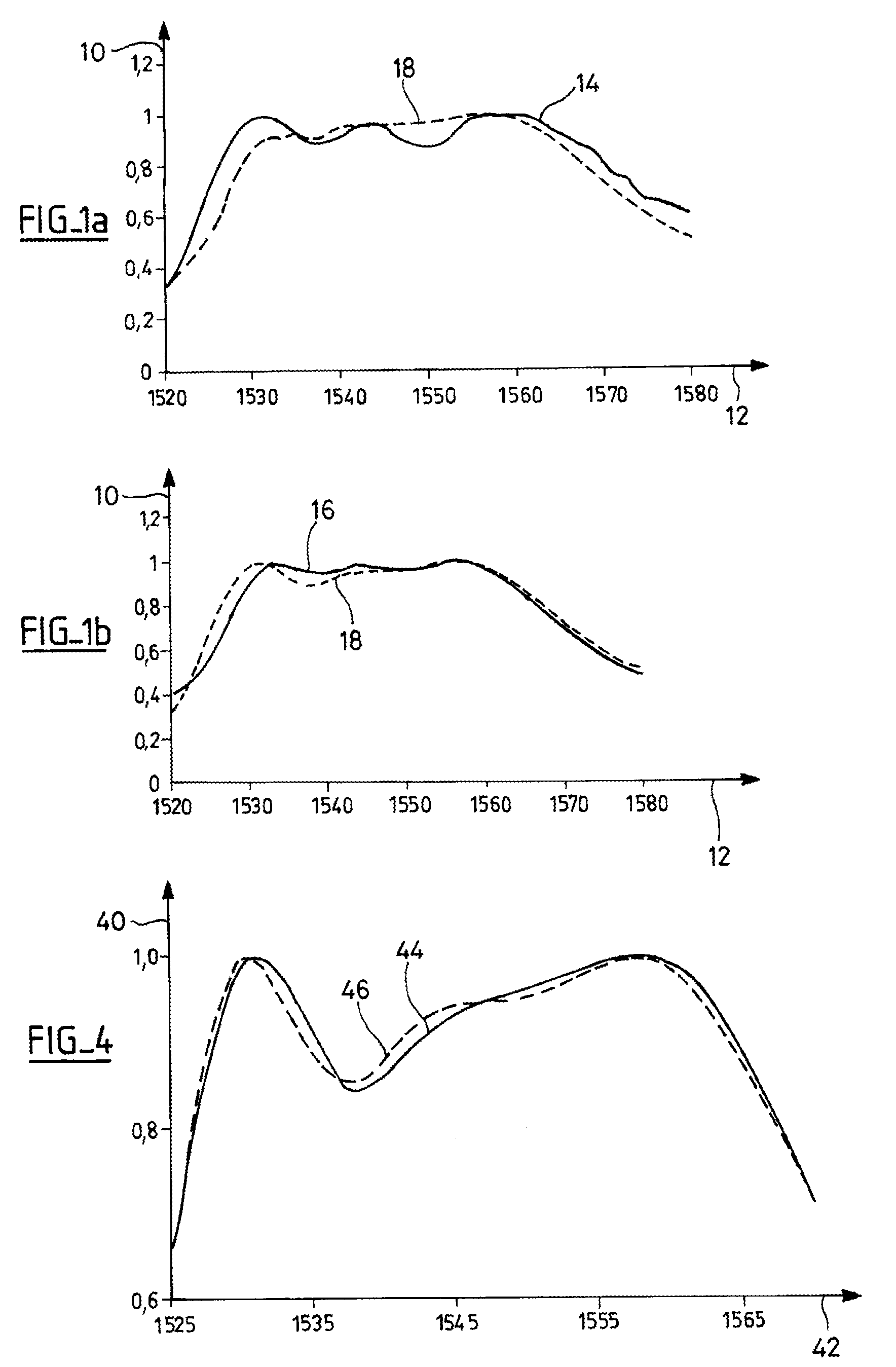
[0031]Types of glass that include bismuth or antimony have particularly interesting characteristics described below with the help of FIGS. 1a and 1b, which represent amplification gains for materials comprising erbium as the doping element and antimony (FIG. 1a) or bismuth (FIG. 1b) as the enhancement element.

[0032]More precisely, these FIGS. 1a and 1b represent the material's amplification gain (y-axis 10) as a function of the wavelength of the amplified signal (x-axis 12) for fibres comprised of antimony (curve 14, FIG. 1a) or bismuth (curve 16, FIG. 1b), these gains being compared to those of a known fibre comprising aluminium as a doping agent (curve 18).

[0033]It thereupon becomes apparent that the respective properties of antimony (Sb) and bismuth (Bi) are interesting for processing an optical signal, to with expanding the curve (Sb) of the gain medium's gain, or flattening said curve (Bi).

[0034]Thus, the usage of a filter intended to flatten the gain of a fibre is lower when t...


PUM

PropertyMeasurementUnit
sizeaaaaaaaaaa
sizeaaaaaaaaaa
sizeaaaaaaaaaa

Abstract

The invention relates to an optical fibre comprising a gain medium which is equipped with: a core (22) which is formed from a transparent material and nanoparticles (24) comprising a doping element and at least one element for enhancing the use of said doping element; and an outer cladding (26) which surrounds the core. The invention is characterised in that the doping element is erbium (Er) and in that the enhancing element is selected from among antimony (Sb), bismuth (Bi) and a combination of antimony (Sb) and bismuth (Bi).
According to the invention, one such fibre is characterised in that the size of the nanoparticles is variable and is between 1 and 500 nanometres inclusive, and preferably greater than 20 nm.

Description

FIELD OF THE INVENTION[0001]The present invention pertains to an optical guide, and in particular an optical fibre, that amplifies telecommunications signals, and a manufacturing method for a preform intended to be shaped into such an optical guide.PRIOR ART[0002]It is known in the art how to use an optical fibre comprising a gain medium to regenerate an optical signal received by that fibre and to retransmit the regenerated optical signal with increased intensity. To do so, such an amplifying fibre comprises:[0003]a core made up of a transparent material incorporating at least one doping element such as rare earth ions like erbium (Er) which amplify the optical signal, and[0004]a cladding surrounding the core, intended to keep the majority of the optical signal within the core.[0005]Conventionally, incorporating doping elements and enhancement elements is done by impregnating porous glass with solutions that include these various doping agents in the form of dissolved salts. This m...

Claims


Application Information

Patent Timeline
Patent Type & Authority Applications(United States)
IPC IPC(8): G02B6/02C03B37/018C03B37/014
CPCC03C3/06C03C4/0071C03C4/10C03C13/045C03C14/004C03C14/006H01S3/169C03C2201/30C03C2201/3476C09K11/7701H01S3/06716H01S3/06754C03C2201/20
Inventor BLANCHANDIN, STEPHANIECOLLET, CHRISTINEPASTOURET, ALAINDE MONREDON, SOPHIEJOLIVET, JEAN-PIERRECHANEAC, CORINNE
Owner ALCATEL LUCENT SAS
Why Eureka
Try Eureka