Hydraulic drive system

a hydraulic drive and drive system technology, applied in the direction of belt/chain/gearing, coupling, belt/chain/gearing, etc., can solve the problems of high operating pressure, low total efficiency, high loss of all components, etc., and achieve low fuel consumption, high performance, and low environmental pollution

Active Publication Date: 2009-06-11
LIEBHERR MACHINES BULLE
View PDF3 Cites 10 Cited by
  • Summary
  • Abstract
  • Description
  • Claims
  • Application Information

AI Technical Summary

Benefits of technology

[0031]Accordingly, the present invention furthermore comprises a vehicle, in particular a movable work machine, in particular an earth-moving machine, having a hydraulic drive system such as was descr...

Problems solved by technology

Adjustable hydraulic displacement machines, in particular axial piston units, however, in principle have high losses at working points with small di...

Method used


Image

  • Hydraulic drive system
  • Hydraulic drive system
  • Hydraulic drive system

Examples


first embodiment

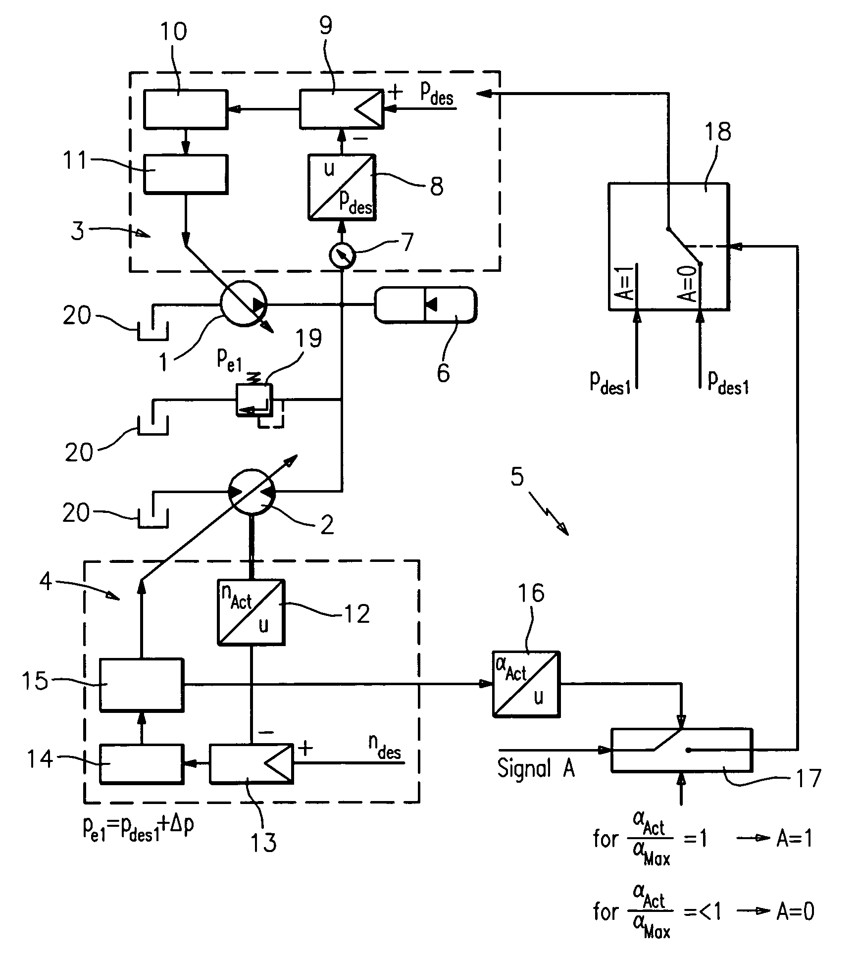
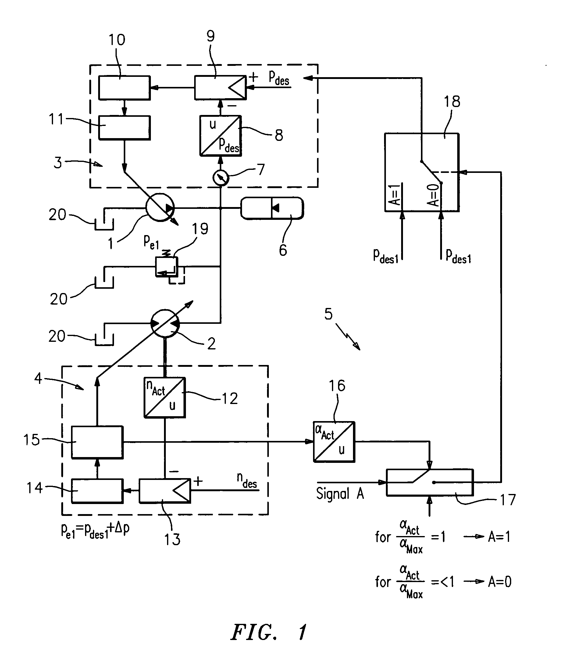
[0035]FIG. 1 shows the circuit diagram of the secondarily regulated hydraulic drive system in accordance with the invention. The open hydraulic circuit is formed in this respect by the hydraulic variable delivery pump 1 as well as by the hydraulic variable capacity motor 2, with the hydraulic pump 1 pumping hydraulic fluid from the hydraulic reservoir 20 to the hydraulic motor 2 via which it flows back to the hydraulic reservoir 20 again. The hydraulic pump 1 is in this connection pressure-regulated via a regulation 5 while the hydraulic motor 2 is regulated via a regulation 4, that is, it is regulated in dependence on its speed, its torque and / or its rotational angle.

[0036]The hydraulic pump 1 is a variable delivery pump having a pumping direction which can be adjusted from 0 to a maximum pumping volume. The pressure regulation device 3 in this respect provides that the hydraulic pump 1 pumps exactly the oil volume flow from the reservoir into the performance network which maintain...

second embodiment

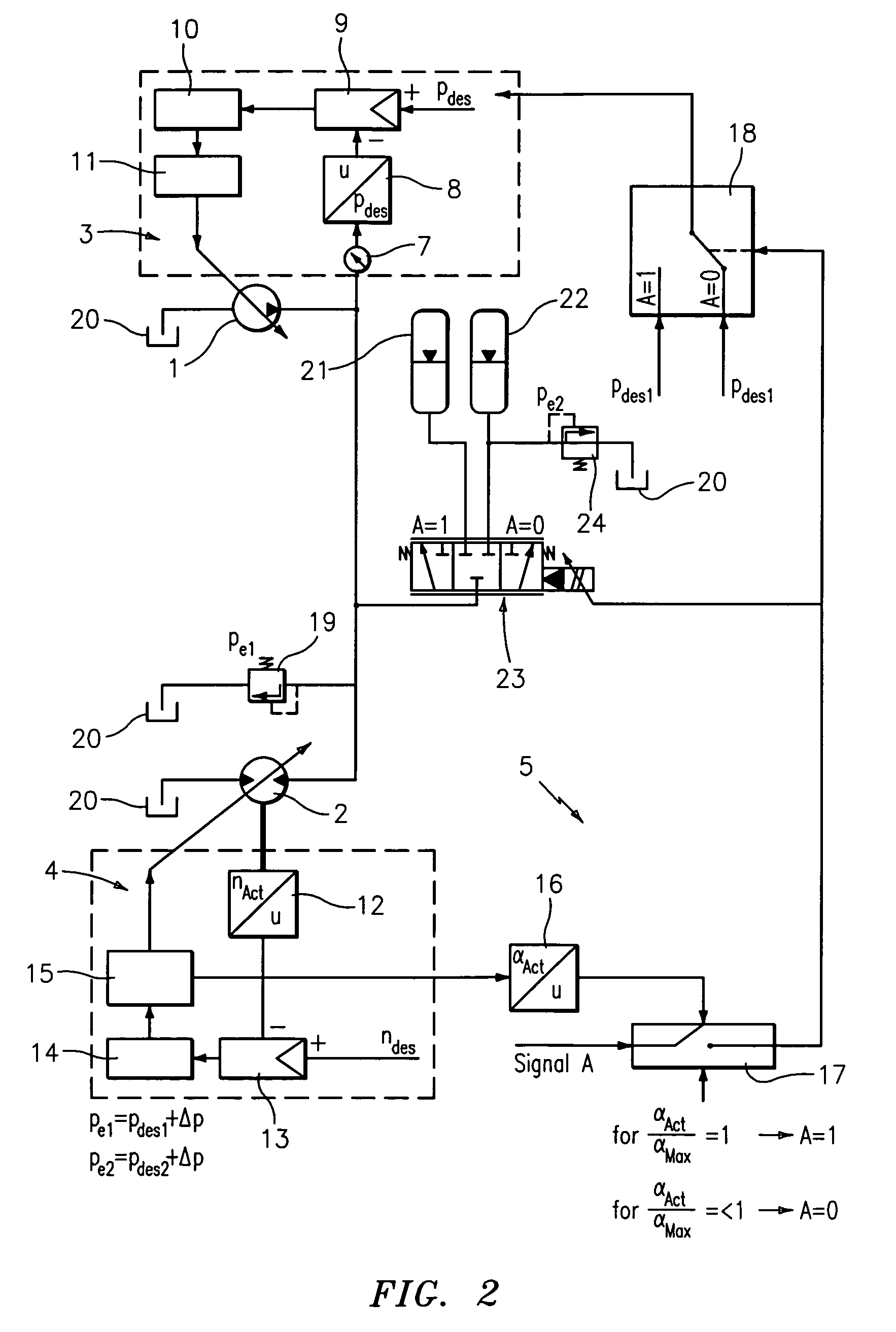
[0047]the hydraulic drive system in accordance with the invention is now shown in FIG. 2 which only differs from the drive system shown in FIG. 1 with respect to the high pressure store. Reference is therefore made to the description with respect to FIG. 1 with respect to all other components.

[0048]In the embodiment shown in FIG. 2, two high pressure stores 21 and 22 are now provided which can be connected alternately via the switching valve 23 to the hydraulic circuit of hydraulic pump 1 and hydraulic motor 2. The switching valve 23 is in this connection likewise controlled by the control 5 in that the switch-over signal A is applied to the switching valve 23 and controls it. For A=0, that is, when no switch-over signal is applied since the adjustment angle αAct is less than the maximum adjustment angle αMax, the switching valve 23 connects the hydraulic circuit to the high pressure store 22 which accordingly has the lower normal pressure pDes2. In this respect, a pressure regulati...


PUM


Abstract

The present invention relates to a hydraulic drive system having a pressure-regulated hydraulic pump for the provision of a system pressure and having a secondarily regulated hydraulic motor. In accordance with the invention, a control is provided which sets the desired system pressure during operation in dependence on an operating parameter of the hydraulic motor.

Description

BACKGROUND OF THE INVENTION[0001]The present invention relates to a hydraulic drive system having a pressure- regulated hydraulic pump for the provision of a system pressure and having a secondarily regulated hydraulic motor.[0002]In such secondarily regulated hydraulic drive systems, the hydraulic pump which is made as a variable delivery pump provides, with the help of a pressure regulation, a system pressure in the line network which is applied to the hydraulic motor. The hydraulic motor which is made as a variable capacity motor then drives a consumer with speed regulation, torque regulation and / or rotational angle regulation. Such a secondarily regulated hydraulic drive system thus includes a pressure-regulated variable delivery pump as a primary unit and a variable capacity motor with speed regulation, torque regulation and / or rotational angle regulation as a secondary unit. A mechanical transmission can be connected before such a hydraulic drive system and connects a drive un...

Claims


Application Information

Patent Timeline
IPC IPC(8): F15B1/027F15B5/00
CPCF04B49/002F04B2205/05F16H61/4096B60W2510/1085F16H61/475F16H2059/6861F16H61/472
Inventor DEEKEN, MICHAELGLINIORZ, VOLKER
Owner LIEBHERR MACHINES BULLE
Why Eureka
Try Eureka