

Ink storing system and ink delivering system
a technology of ink storage and ink delivery, which is applied in the field of ink storage system and ink delivery system, can solve the problems of air permeating through the walls of ink containers and/or ink delivery passages, forming bubbles, and air having dissolved into ink to form bubbles, etc., and achieves the effect of improving the spatial efficiency of ink storage, and reducing with ink consumption
- Summary
- Abstract
- Description
- Claims
- Application Information
AI Technical Summary
Benefits of technology
Problems solved by technology
Method used
Image

Examples
embodiment 1
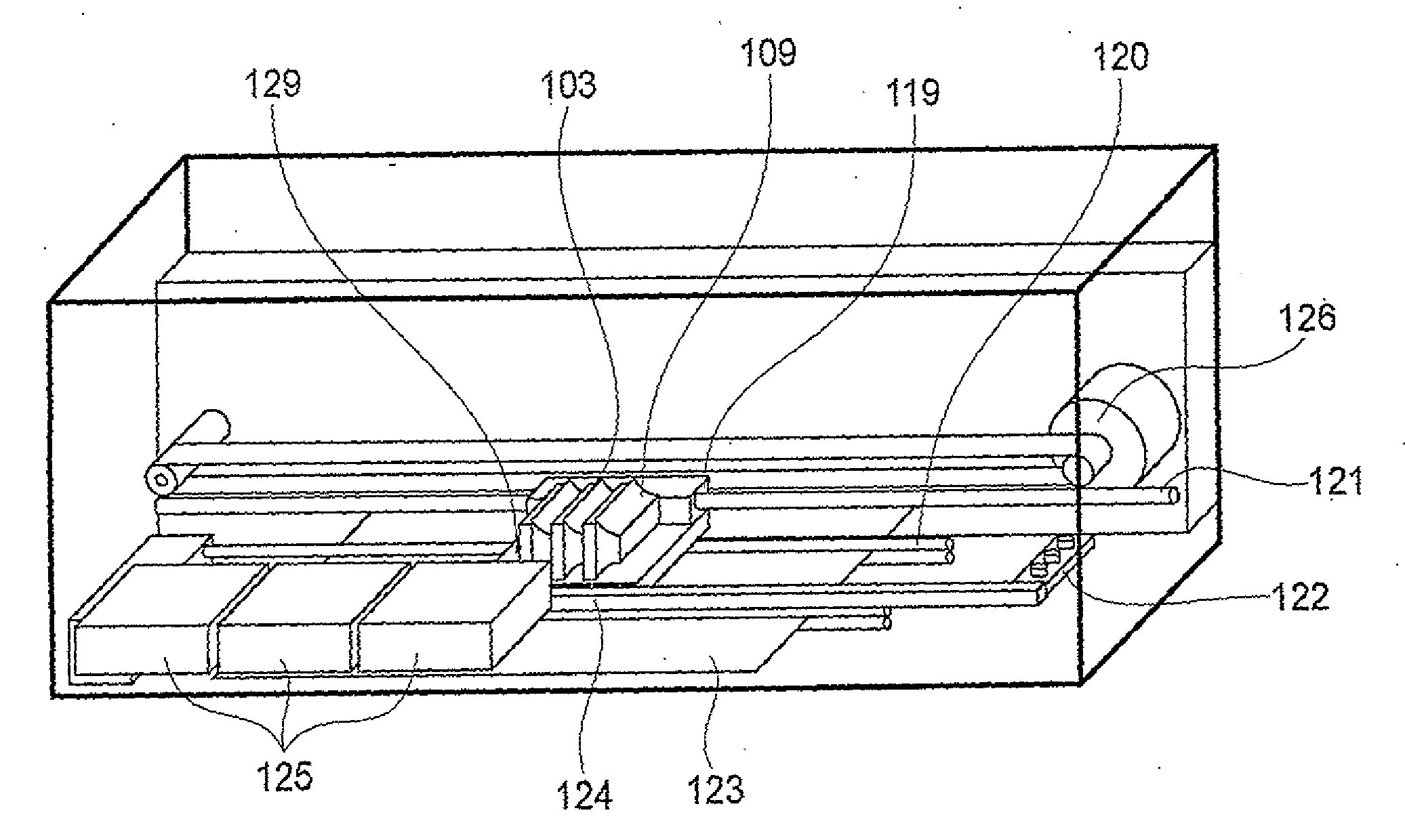
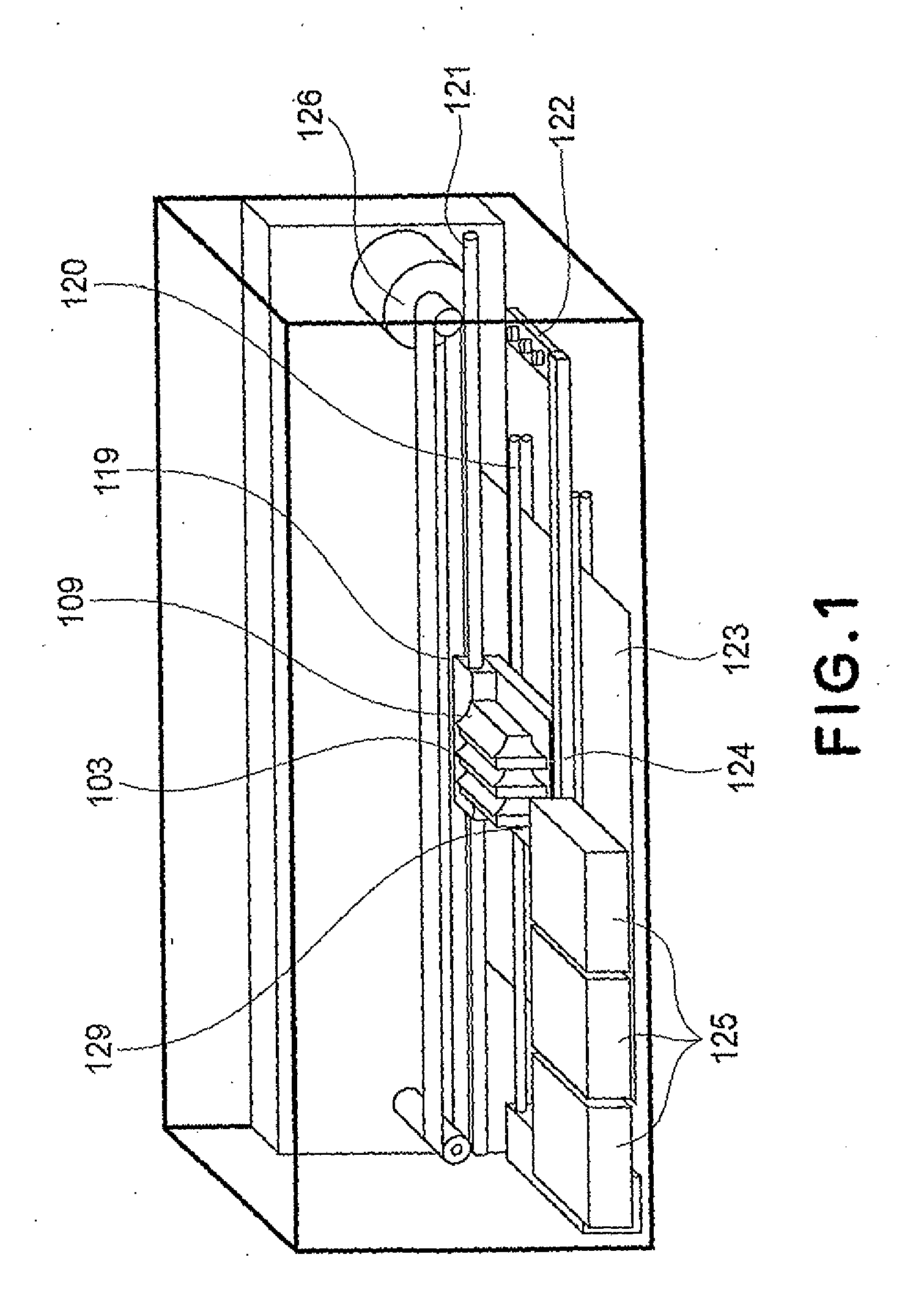
[0033]First, referring to FIG. 1 the general structure of the ink jet recording apparatus in the first embodiment of the present invention will be described.
[0034]The ink jet recording apparatus in this embodiment of the present invention has a recording head (unshown), an ink supply source 125 as a main ink container, a subordinate ink container 103 (ink storage portion), and a carriage 119. It is structured so that the subordinate ink container 103 is mounted on the carriage 119, whereas the ink supply source 125 is located off the carriage 119. Thus, the ink jet recording apparatus is provided with an ink delivery tube 124 for guiding the ink in the main container 125 to a preset location, and a connective portion 122, by which the ink delivery tube 124 is connected to the subordinate ink container 103 in order to deliver the ink to the subordinate ink container 103. The ink jet recording apparatus is structured so that as the carriage 119 is moved to a home position or a preset ...
embodiment 2
[0053]FIGS. 8(a)-8(c) are schematic sectional views of the recording head cartridge and gas purging unit in the second embodiment of the present invention.
[0054]The ink container 103 in this embodiment is the same in structure as that in the first embodiment.
[0055]However, the negative pressure storing portion 130 in this embodiment is different from that in the first embodiment, in that it is a part of the main assembly of an ink jet recording apparatus.
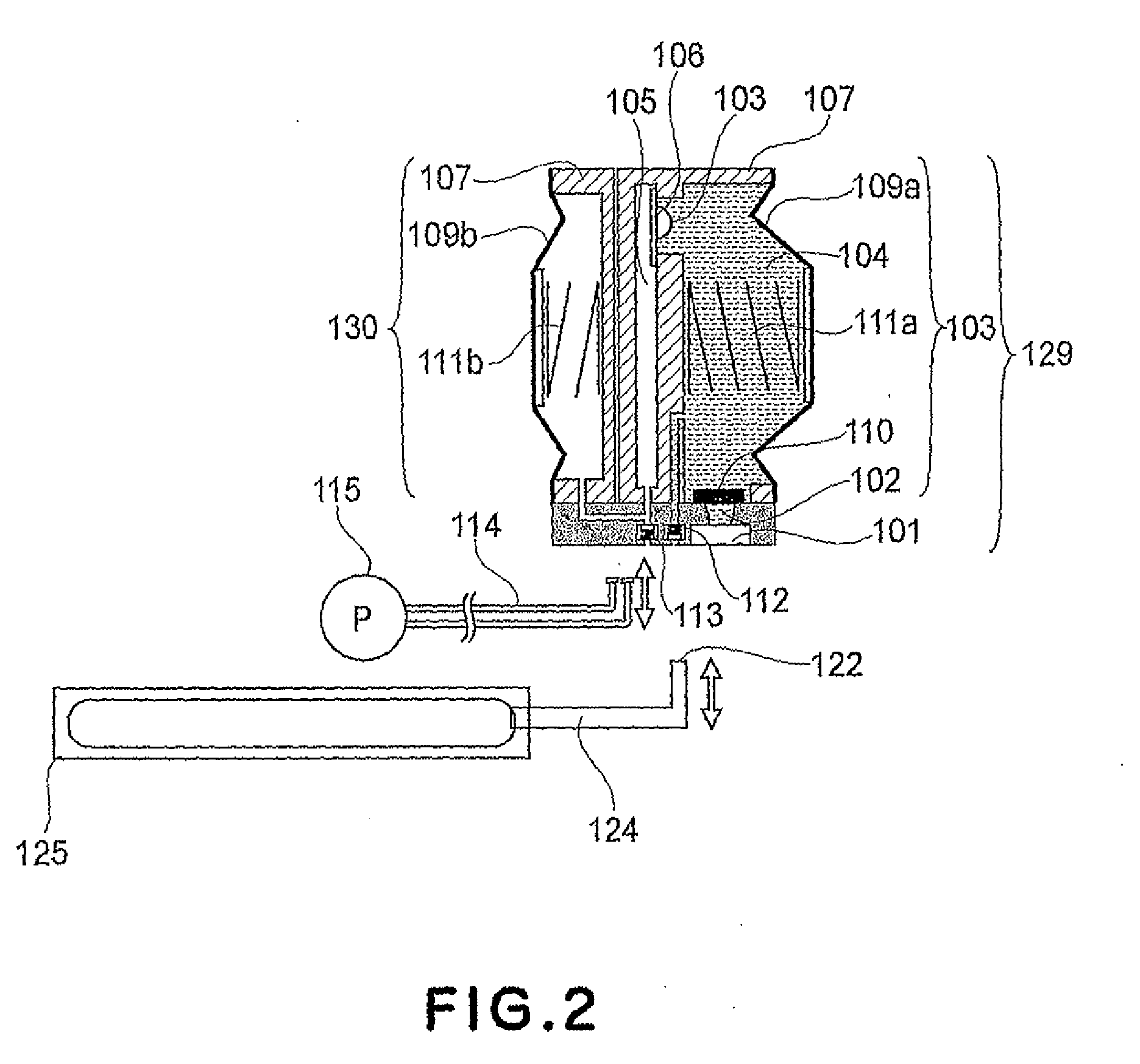
[0056]This negative pressure storing portion 130 is connected to a connective tube 114 (gas passage) which is in connection with the suction pump 115. In terms of the lengthwise direction of the connective tube 114, the negative pressure storing portion 130 is positioned near the home position the recording head unit, and serves as a gas purging unit 116. The gas purging unit 116 is connectible with the air outlet 113 of the ink container 103. When the ink jet recording apparatus is not recording, for example, while it is on standby...
embodiment 3
[0062]FIGS. 10(a)-10(c) are schematic sectional views of the recording head cartridge and gas purging unit in the third embodiment of the present invention.
[0063]The ink container 103 in this embodiment is the same in structure as those in the first and second embodiments. However, the negative pressure storing portion 130 in this embodiment is different from that in the first embodiment, in that it is a part of the main assembly of an ink jet recording apparatus as it is in the second embodiment.
[0064]That is, the negative pressure storing portion 130 in this embodiment is connected to the connective tube 114 which is in connection with the suction pump 115. In terms of the lengthwise direction of the passage 114, the negative pressure storing portion 130 is positioned near the home position of the recording head unit 129, and serves as a gas purging unit 116.
[0065]The gas purging unit 116 is connectable with the air outlet 113 of the ink container 103. When the ink jet recording a...
PUM
 Abstract
Description
Claims
Application Information