Refrigerator and operating method of the same

Inactive Publication Date: 2009-07-02
SHARP KK
View PDF10 Cites 6 Cited by
  • Summary
  • Abstract
  • Description
  • Claims
  • Application Information

AI Technical Summary

Benefits of technology

[0032]The invention can eliminate the bubbles that occur in the liquid phase fluid when the operation of the refrigerator stops for a long time. Consequently, such a problem is prevented that the liquid phase circulation pump runs idle, and the liquid phase fluid does not circulate through the liquid phase c

Problems solved by technology

In recent years, therefore, specified flon (i.e., chlorofluorocarbon) and alternative flon have been used, and the production

Method used


Image

  • Refrigerator and operating method of the same
  • Refrigerator and operating method of the same
  • Refrigerator and operating method of the same

Examples


Example

First Embodiment

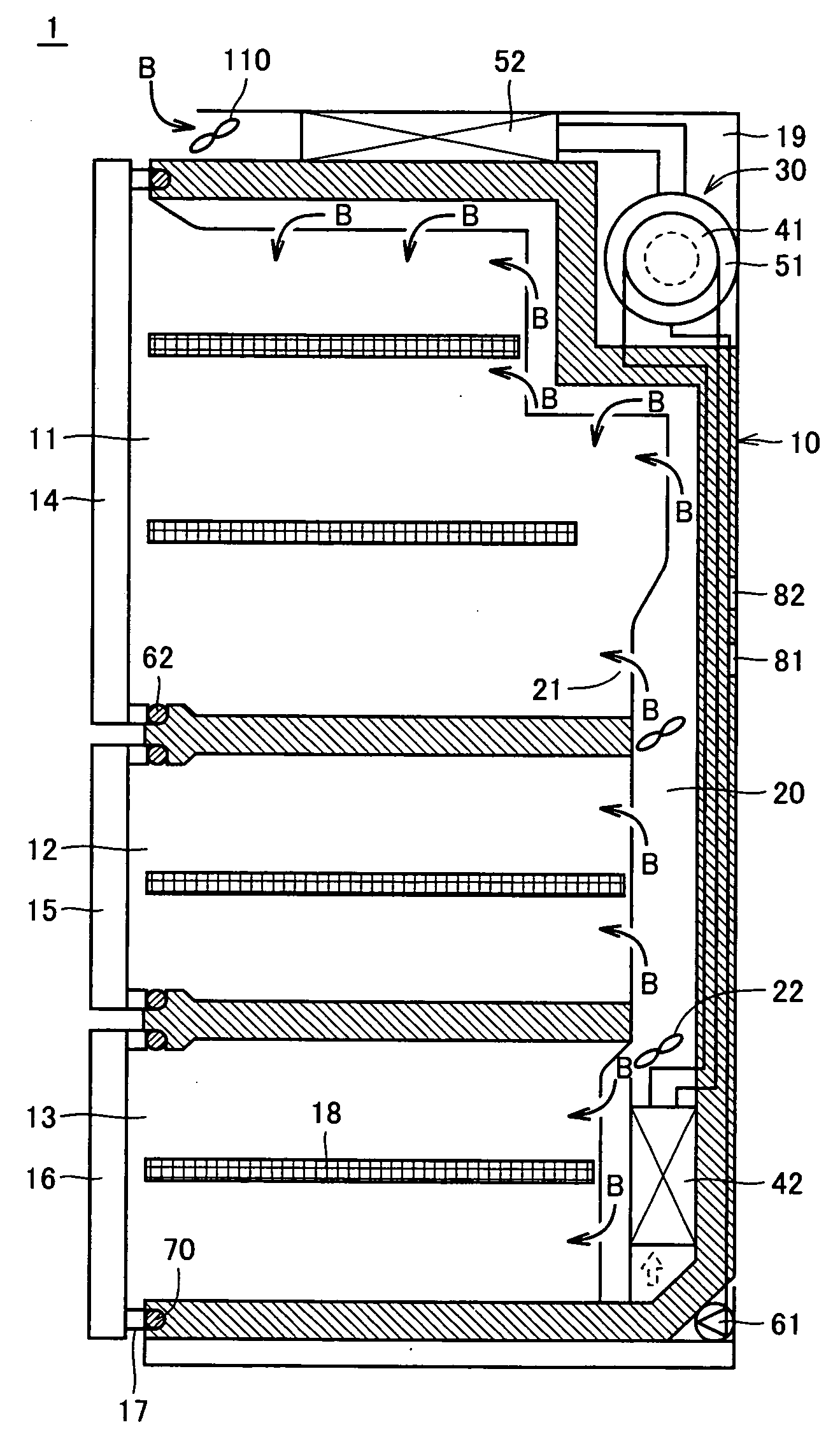
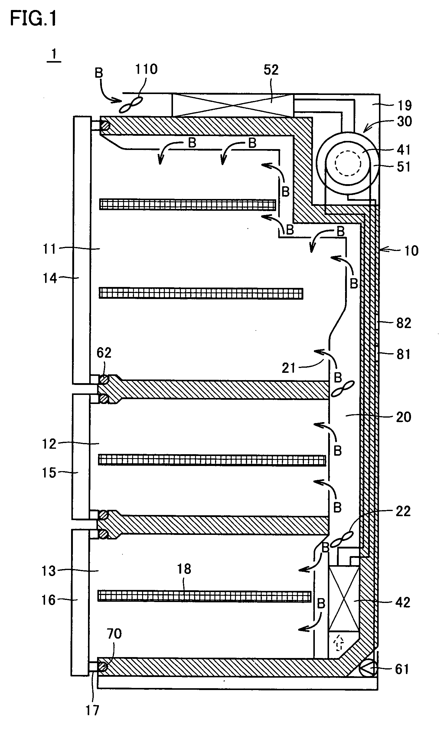
[0045]FIG. 1 is a cross section showing a schematic structure of a refrigerator of this embodiment. FIG. 2 shows a piping structure of the refrigerator of this embodiment. A refrigerator 1 is aimed at food storage, and includes a housing 10 of a heat-insulating structure. Three cooling rooms or compartments 11, 12 and 13 are formed at different levels in housing 10, respectively.

[0046]Cooling rooms 11, 12 and 13 have openings on a front side (left side in FIG. 1) of housing 10, respectively. These openings are closed by openable heat-insulating doors 14, 15 and 16, respectively. Heat-insulating doors 14, 15 and 16 are provided at their rear surfaces with packings 17 surrounding the openings of cooling rooms 11, 12 and 13, respectively. Shelves 18 suitable for types of foods to be stored are appropriately arranged in cooling rooms 11, 12 and 13.

[0047]A cooling system and a heat radiating system that include a Stirling refrigerating engine 30 as a main component are ar...

Example

Second Embodiment

[0088]A refrigerator of a second embodiment will now be described. The refrigerator of the second embodiment has substantially the same structure as that of the first embodiment already described. Therefore, the second embodiment will be described only in connection with portions different from those in the first embodiment.

[0089]In the refrigerator of the first embodiment, the additional and independent heating device is not employed, and the operation method of the refrigerating machine, i.e., freezing machine is changed to apply the pressure to the gas phase fluid flowing in high temperature side natural circulation circuit 50. Instead of these structure and method, the second embodiment employ heating means (e.g., heater) 100 that can apply heat to the gas phase fluid flowing through high temperature side natural circulation circuit 50, as specifically illustrated in FIG. 7. By operating this heating means 100, it is possible to heat and thereby pressurize the g...

Example

[0100]A third embodiment of the invention will now be described. The refrigerator of this embodiment has substantially the same structure as the refrigerators of the first and second embodiments. Therefore, the following description will be given on only the portion of this embodiment different from the first and second embodiments.

[0101]The start processing performed by control device 90 of Stirling refrigerating engine 30 of the third embodiment will be described with reference to a flowchart of FIG. 9.

[0102]In the start processing, it is first determined in S21 whether a switch of the freezing machine, i.e., Stirling refrigerating engine 30 is on or not. When the start switch of the refrigerating machine is not on in S21, processing in S33 is executed. When the start switch of Stirling refrigerating engine 30 is on in S21, processing in S22 is executed. In S22, Stirling refrigerating engine 30 starts the operation. Then, in S23, the output of circulation pump 61 is set to 0 or P1...


PUM


Abstract

When a Stirling refrigerating engine for cooling a refrigerator starts, an operation is performed such that a gas-phase fluid flowing through a natural circulation circuit on a high temperature side attains a temperature higher than that in a normal operation. More specifically, the Stirling refrigerating engine operates with a piston drive speed higher than a normal speed, or a fan motor arranged for a condenser on the high temperature side stops. Thereby, a gas/liquid coexistent refrigerant in a high temperature side evaporator attains a pressure higher than a normal pressure. Thereby, a liquid phase fluid in a forced-circulation circuit on a high temperature side also attains a pressure higher than a normal pressure so that bubbles produced in the liquid phase fluid disappear, and a circulation pump can start.

Description

TECHNICAL FIELD[0001]The present invention relates to a refrigerator having a cooling space for cooling stored goods as well as an operating method of the same.BACKGROUND ART[0002]General refrigerators have widely employed vapor compression refrigerating engines. The vapor compression refrigerating engine utilizes condensation and evaporation of a flon gas to achieve a low temperature. Since the flon gas has neither flammability nor explosibility, and has low corrosivity, it can be used very readily as a refrigerant. However, the flon gas has a high chemical stability. Therefore, when the flon gas is released into an atmosphere, it reaches the stratosphere to destroy the ozone layer. In recent years, therefore, specified flon (i.e., chlorofluorocarbon) and alternative flon have been used, and the production of the flon gas has been restricted on a worldwide basis.[0003]In recent years, therefore, attention has been given to a Stirling refrigerating engine as a refrigeration techniqu...

Claims


Application Information

Patent Timeline
IPC IPC(8): F25B1/00
CPCF25B9/14Y02B40/32F25B2600/111F25B2600/13F25B2700/02F25D11/025F25D17/062F25D21/04F25D23/003F25D29/00F25D2317/0682F25D2400/02F25D2700/14Y02B30/743Y02B30/745F25B2500/26Y02B30/70Y02B40/00
Inventor ZHANG, HENGLIANGCHEN, WEI
Owner SHARP KK
Why Eureka
Try Eureka