Nondestructive capture of hypervelocity projectiles

a hypervelocity and projectile technology, applied in the direction of superconducting magnets/coils, magnets, magnetic bodies, etc., can solve the problems of limited projectile mass and speed only by the required stopping distance, and the field produced by conventional permanent magnets will not stop projectiles in a practical distance , to achieve the effect of inhibiting induction

Inactive Publication Date: 2009-12-10
SIERRA LOBO
View PDF30 Cites 14 Cited by
  • Summary
  • Abstract
  • Description
  • Claims
  • Application Information

AI Technical Summary

Benefits of technology

[0009]A method of decelerating a projectile is also disclosed, which includes the following steps: a) generating a first magnetic field that moves with the projectile; b) directing the projectile along a path that is encircled by a closed conductive pathway; and c) inhibiting induction of a current through the conductive pathway in a direction that would generate a magnetic field of ...

Problems solved by technology

Its use is limited by the field strength of the magnetic-field source in the projectile, because this limits the available braking force.
The fields produced by permanent magnets may be sufficient for conventional applications, with projectile masses and speeds limited only by the required stopping distance and limitations on brake system mass.
However, at the speeds and ma...

Method used


Image

  • Nondestructive capture of hypervelocity projectiles
  • Nondestructive capture of hypervelocity projectiles
  • Nondestructive capture of hypervelocity projectiles

Examples


examples

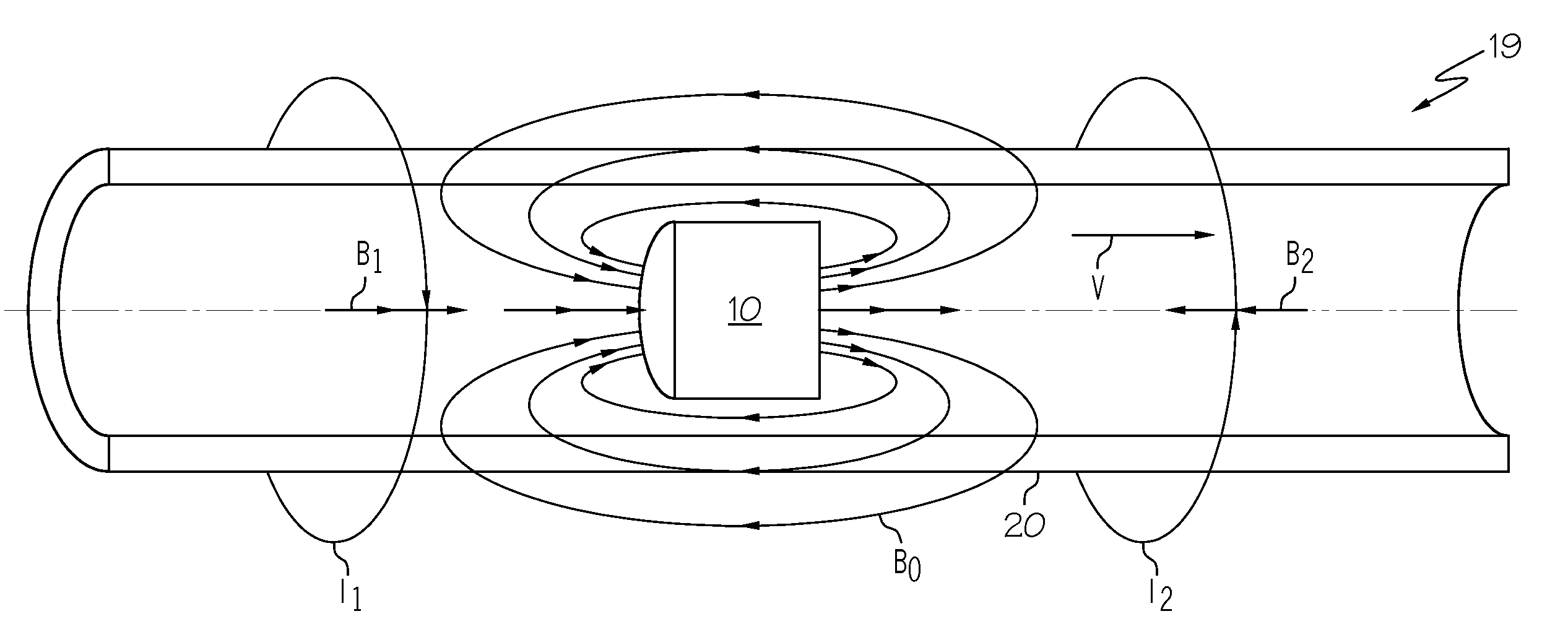
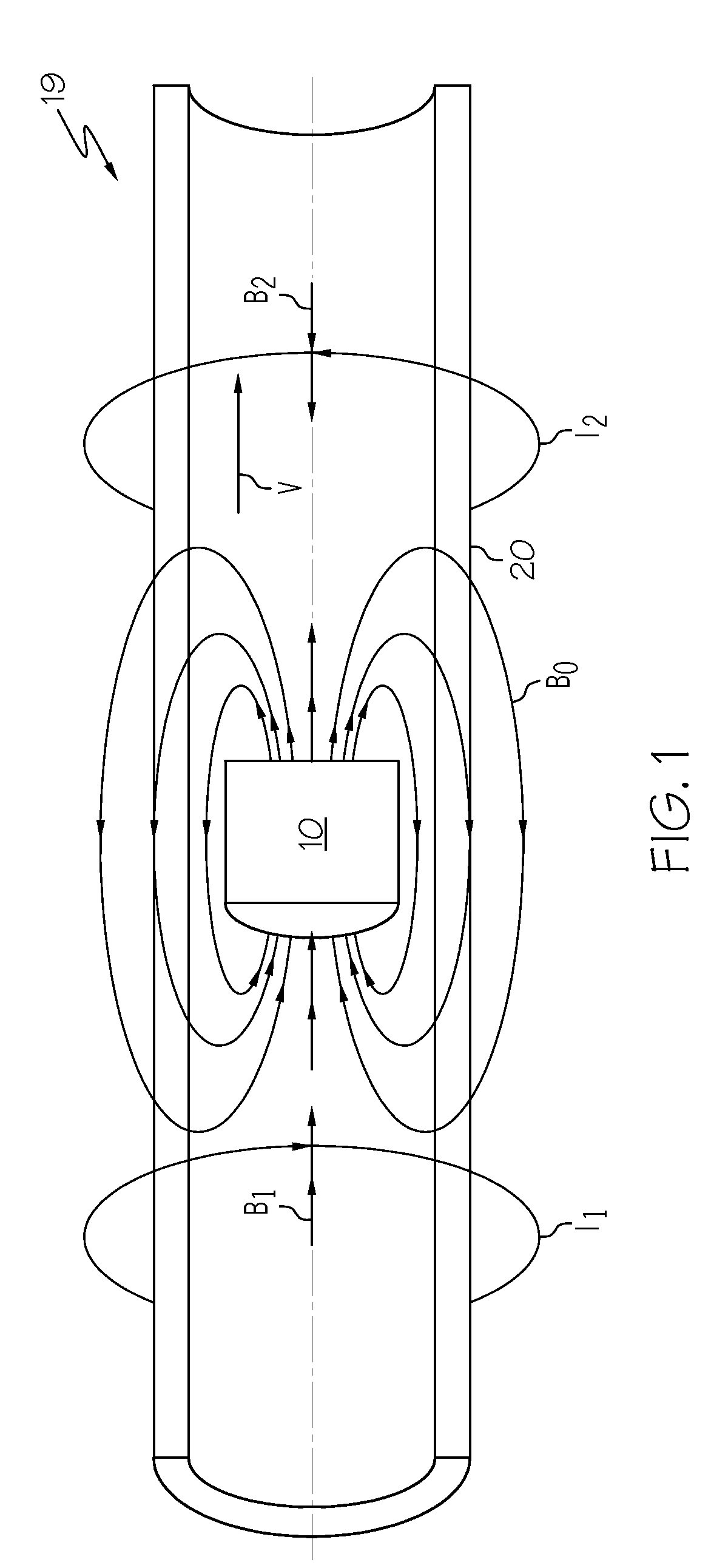
[0079]Bennett et al., “Electromagnetic Braking of a Metallic Projectile in Flight,”IEEE Transactions on Magnetics, vol. MAG-21, p. 1250 (1985), incorporated herein by reference, provided correlations for determining the required stopping distance for a projectile of known momentum (mass times speed) or energy based on the strength of the magnetic field B0 associated with the projectile 10 traveling through a conductive tube 20. In Bennett, the configuration was different from those disclosed herein where the field source 100 is carried on the projectile 10. In Bennett the projectile carries a passive metal sleeve but does not generate or have associated with it a magnetic field that moves with the projectile. Instead, the catch tube in Bennett carries a magnet that induces cooperating magnetic fields in the traveling projectile to exert a braking force. In Bennett the magnet must extend the entire length of the catch tube, presenting a significant initial and operating expense. Benn...


PUM


Abstract

Apparatus for inductive braking of a projectile are disclosed. Embodiments include a receiver that has a unidirectional conductor having a closed conductive pathway that encircles a passageway for a moving projectile. The unidirectional conductor permits current to flow through it in substantially only one direction around the passageway. As the projectile and its associated magnetic field move past the unidirectional conductor, the moving magnetic field induces a current flow through the closed conductive pathway, which in turn generates a magnetic field behind the projectile having the same polarity as the projectile's field. The two fields attract one another, which both exerts a braking force on the projectile and tends to align the two fields. Alignment of these fields centers the projectile away from the passageway wall. Because the unidirectional conductor permits current to flow in substantially only the direction that produces a field having the same polarity as the moving field, the opposite-polarity repulsive magnetic field that would otherwise be generated ahead of the projectile, which would otherwise deflect the projectile from its path, is suppressed. Methods of inductive braking are also disclosed.

Description

[0001]This application claims the benefit of U.S. Provisional Application Ser. No. 61 / 059,883 filed Jun. 9, 2008, the contents of which are incorporated herein by reference.BACKGROUND OF INVENTION[0002]1. Field of the Invention[0003]The invention relates to the conversion of kinetic energy of a projectile into thermal energy to slow the projectile via inductive braking. More particularly it relates to an improved inductive-braking apparatus for nondestructive capture of hypervelocity projectiles.[0004]2. Description of Related Art[0005]Inductive braking (also referred to as magnetic braking) relies on the generation of induced magnetic fields to supply braking force to a moving projectile, which has its own magnetic field. The moving field source, associated with the projectile, can be a permanent or electro-magnet secured to a projectile it is desired to stop, moves along a path adjacent a conductor, for example through the hollow bore of a cylindrical sleeve or other long enclosur...

Claims


Application Information

Patent Timeline
IPC IPC(8): H01F6/06
CPCF41B6/00H01F2027/408H01F6/06F41J13/00
Inventor PUTMAN, PHILIP TRAVISSALAMA, KAMEL
Owner SIERRA LOBO
Why Eureka
Try Eureka