Dryer comprising a heat sink and a condensate container

Active Publication Date: 2009-12-31
BSH BOSCH & SIEMENS HAUSGERAETE GMBH
View PDF1 Cites 11 Cited by
  • Summary
  • Abstract
  • Description
  • Claims
  • Application Information

AI Technical Summary

Benefits of technology

[0005]It is an object of the invention to alleviate the problem of limited cleaning effect and p

Problems solved by technology

These large cross sections will cause low limits to pressure and velocity of the co

Method used


Image

  • Dryer comprising a heat sink and a condensate container
  • Dryer comprising a heat sink and a condensate container
  • Dryer comprising a heat sink and a condensate container

Examples


Embodiment Construction

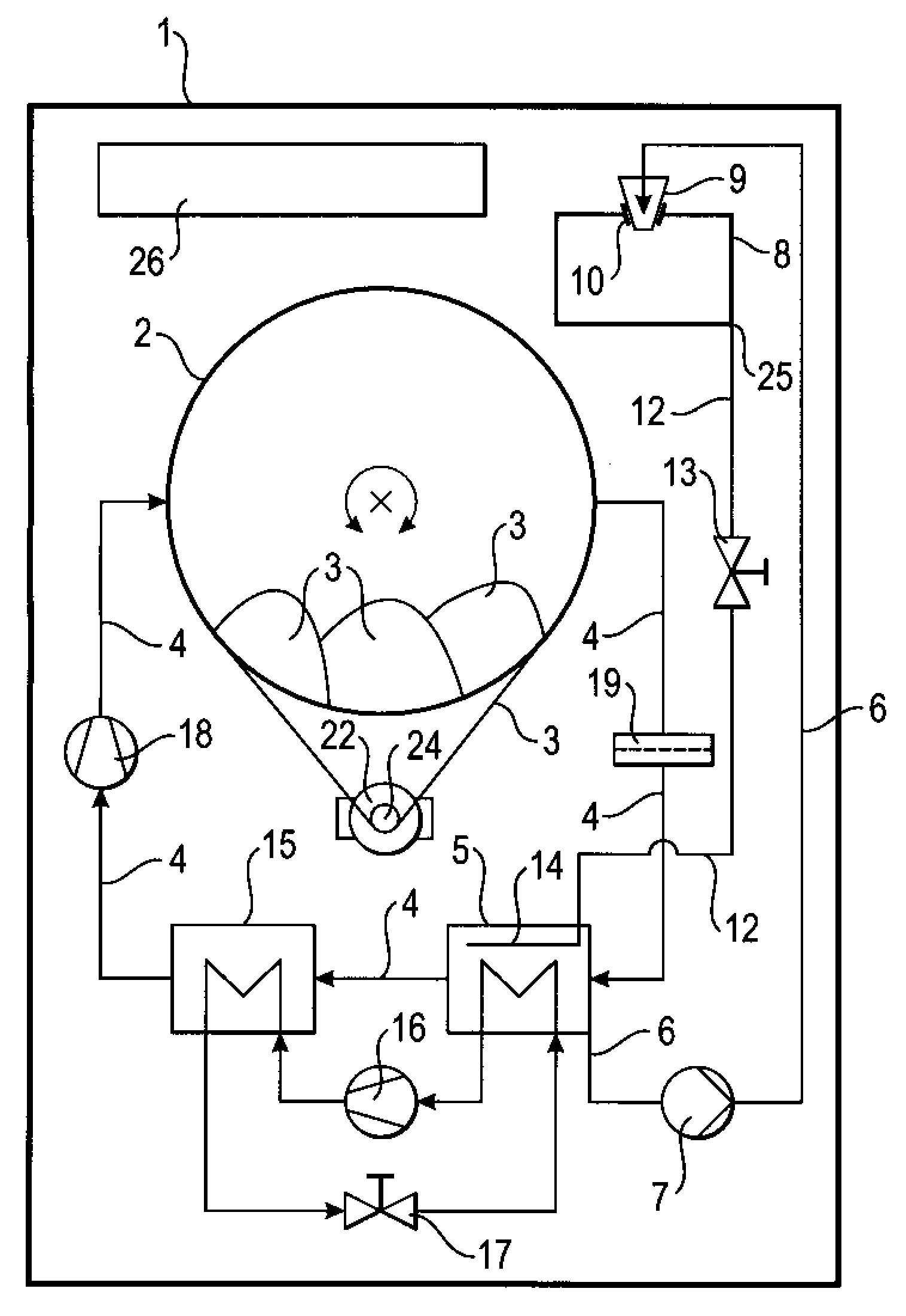
[0025]According to FIG. 1, the dryer 1 shown is configured as a laundry dryer 1. It includes a drying chamber 2 that is embodied as a rotatable drum 2 and contains articles 3 to be dried, namely humid laundry 3. Process air is guided through the drying chamber 2 and around the laundry 3 within a closed circuit which is defined by process air guide 4. The process air guide 4 includes means to drive the process air, in particular a blower 18, means to heat the process air prior to introducing it into the drying chamber 2, which means are in particular a heat source 15. Further, the process air guide includes means to cool the process air subsequent to passing through the drum 2, in particular the heat sink 5.

[0026]As the process air is guided through the heat sink 5, humidity collected by the process air while passing along the humid laundry 3 is precipitated from the process air as a liquid condensate by extracting heat from the process air as it passes through the heat sink 5. Conde...


PUM


Abstract

A dryer includes a drying chamber, a process air guide that guides process air along the articles to pick up humidity from them, a heat sink in the process air guide that precipitates humidity from the process air as a condensate, and a condensate collector with a condensate container having an insert that is permeable to the condensate and that projects through an opening into the condensate container for transferring the condensate to and from the condensate container. The insert includes a first filter that filters particles from the condensate prior to storing the condensate in the condensate container.

Description

BACKGROUND OF THE INVENTION[0001]The invention relates to a dryer comprising a drying chamber to contain articles to be dried, a process air guide for guiding process air along the articles to pick up humidity from them, a heat sink disposed in the process air guide for precipitating the humidity the comprising a condensate container to contain the condensate.[0002]A dryer of such type is apparent from each of the patent publications DE 37 38 031 C2, WO 2007 / 093461 A1, WO 2007 / 093467 A1, and WO 2007 / 093468 A1.[0003]According to each of these documents, the condensate collected is applied to clean at least one component of the dryer from lint, in particular a heat sink that is used to extract heat from a flow of process air which is being circulated through the articles to be dried, to precipitate humidity collected from the articles as a condensate. The heat sink in particular is a component of a heat pump, namely an evaporator heat exchanger wherein the heat extracted from the proc...

Claims


Application Information

Patent Timeline
IPC IPC(8): F26B11/02
CPCD06F58/24
Inventor BALERDI AZPILICUETA, PILARSTEFFENS, GUENTER
Owner BSH BOSCH & SIEMENS HAUSGERAETE GMBH
Why Eureka
Try Eureka