Image processing with modified ramp signal

Inactive Publication Date: 2003-02-18
QINETIQ LTD
View PDF7 Cites 2 Cited by
  • Summary
  • Abstract
  • Description
  • Claims
  • Application Information

AI Technical Summary

Benefits of technology

An object of the present invention is to provide an improved imager and method of image pro

Problems solved by technology

A problem with the construction of such arrays arises because the gain of each detector/amplifier combination will be different due to manufacturing tolerances.
Thus, if the output image was simply produced by feeding the output of the detectors straight to the pixels of a monitor, the image would be highly noisy.
A further problem arises when the choice of detector requires the use of a bias voltage applied across the detector.
If the voltage ramp is left unchecked it may eventually destroy the amplifier, and at the least would reduce the dynamic range of the device.
On each reset the output returns to a chosen voltage, but due

Method used


Image

  • Image processing with modified ramp signal
  • Image processing with modified ramp signal
  • Image processing with modified ramp signal

Examples


Example

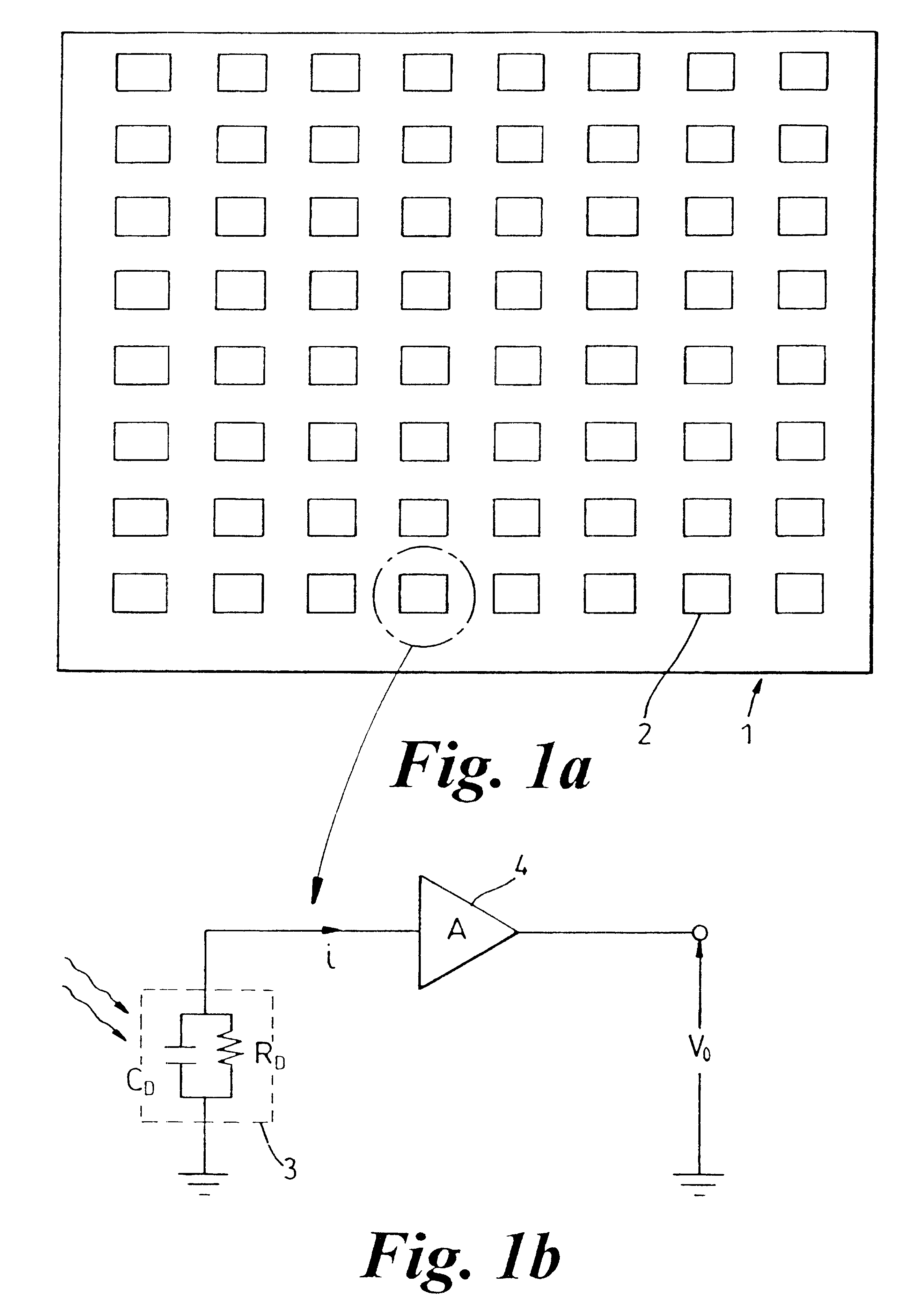
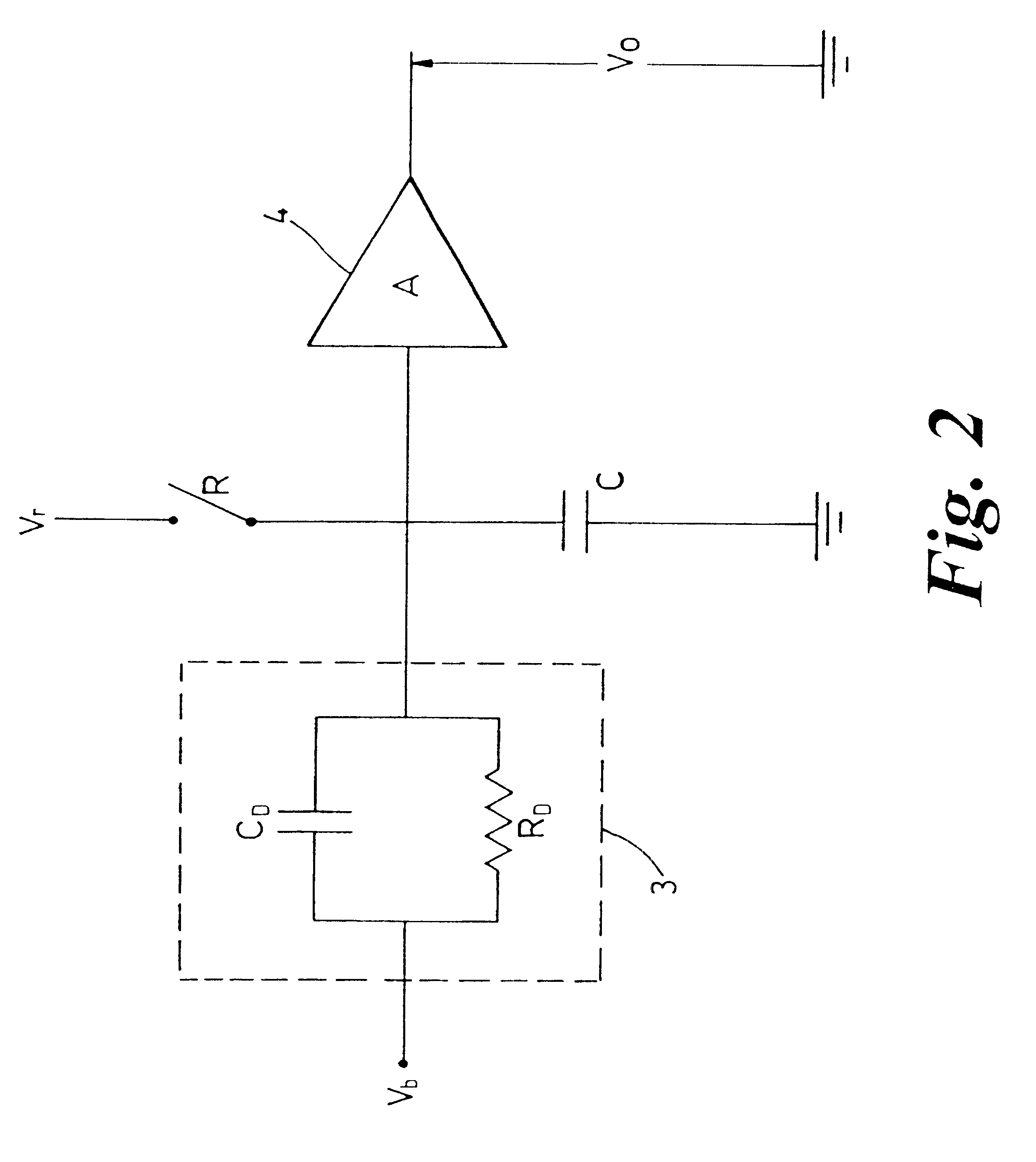
FIG. 1a shows an array 1 of sensors 2 for use in producing an image of the signature of a scene in the thermal (infra-red) range. Each sensor 2 of the array comprises an uncooled detector element 3 and an associated amplifier 4 as shown in FIG. 1b. The detector can be represented as a capacitance C.sub.D in parallel with an (undesirable) parasitic resistance R.sub.D.

In the case of a pyroelectric array, no bias voltage is applied to the detector element 3, and a current is generated in response to radiation incident upon the detector. This is amplified by the charge amplifier 4 to produce an output voltage.

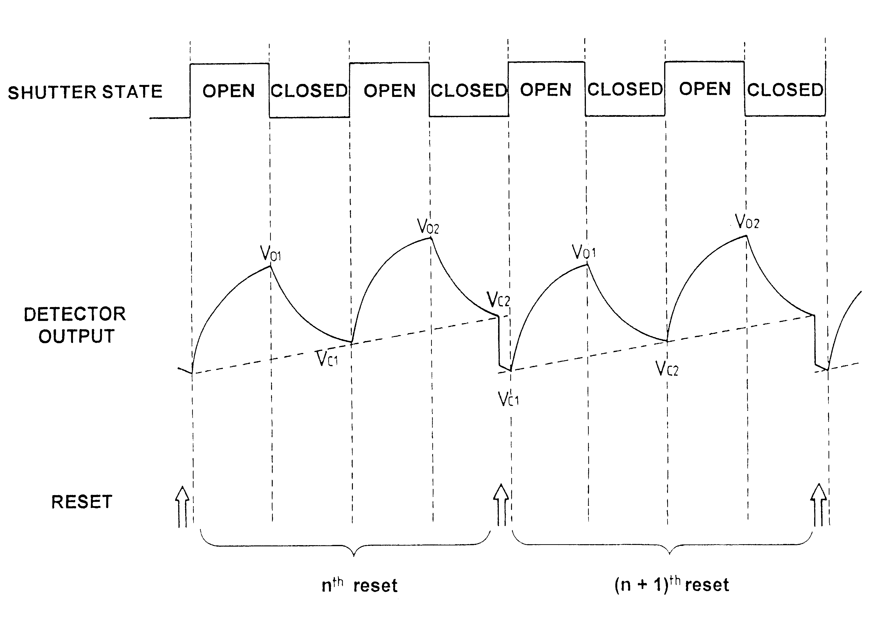
In order to increase the sensitivity of the array 1, the radiation flux incident upon each detector element 3 is modulated by a shutter (not shown). In its open position, the shutter allows radiation to fall upon a detector. In its closed position, the radiation is either partially or totally prevented from reaching the detector. By comparing the voltage signals output from the amp...


PUM


Abstract

An imager is disclosed comprising: one or more detectors, a shutter adapted to open and close periodically to modulate the radiation incident upon the detector element to produce a sequence of alternating open fields and closed fields, said detector being adapted to produce a first pair of output signals V.sub.o1 and V.sub.c1 comprising an open field and a closed field, and a second pair of output signals V.sub.o2 and V.sub.c2 comprising an open and a closed field, a reset device adapted to reset the output of the detecting element to a predetermined voltage after the output signals of V.sub.o1, V.sub.c1, V.sub.o2 and V.sub.c2 have all been obtained, there being no reset of the output of the detecting element between the output signals V.sub.o1, V.sub.c1, V.sub.o2 and V.sub.c2, and a processor adapted to process said first and second pairs of output signals to produce a first and a second processed image signal from the detecting element, the first processed image signal corresponding to the first pair of fields and the second processed image signal corresponding to the second pair of fields. The four signals provide sufficient information to produce images,which are free from reset KTC noise whilst removing the effects of ramp voltages produced by current leakage across the detectors.

Description

BACKGROUND OF THE INVENTION1. Field of the InventionThis invention relates to improvements in image processing techniques, and in particular to an improved method of producing an image from an array of detectors, and to apparatus arranged to perform the processing. It is particularly, but not exclusively, applicable to the field of uncooled thermal imaging.2. Discussion of Prior ArtMany types of detector are known which are sensitive to incident radiation such as infra-red light. Typically, these detectors comprise a sensing element which produces an electrical output signal dependent upon the flux of the radiation incident upon the sensing element. By constructing an array of such detectors, and providing suitable focusing lenses, a two dimensional image of a scene can be produced. In its simplest form, each detector in an array produces an output signal dependent upon the amplitude of incident radiation which is amplified and used to drive a pixel in a VDU, television screen or mo...

Claims


Application Information

Patent Timeline
IPC IPC(8): H04N5/33H04N5/217G01J5/48H04N5/363H04N5/365
CPCH04N5/33H04N5/3651H04N5/363H04N25/65H04N25/671
Inventor MANNING, PAUL A
Owner QINETIQ LTD
Why Eureka
Try Eureka