Light guide for endoscopes

a technology of endoscopes and light guides, which is applied in the field of light guides for endoscopes, can solve the problems of deterioration of the durability of the light guides, inability to meet the needs of patients, and easy breakage of optical fibers, so as to achieve greater light utilization efficiency, greater illumination range, and greater apertures.

Inactive Publication Date: 2009-12-31
FUJIFILM CORP
View PDF2 Cites 1 Cited by
  • Summary
  • Abstract
  • Description
  • Claims
  • Application Information

AI Technical Summary

Benefits of technology

[0025]In multi mode fibers, there is a relationship that the product of the beam diameter (core diameter) of an input or output light beam and the angle of beam spread θ is maintained. Note that the numerical apertures of optical fibers are defined as NA=sin θ. In the light guide for endoscopes of the present invention, at least one of the light input portion and the light output portion, which are constituted by a plurality of bundled multi mode optical fibers, is of a tapered shape, while having the same number of optical fibers as at other portions of the light guide. Therefore, the core diameter at the light input portion and / or the light output portion is smaller than that of the other portions.
[0026]Based on the aforementioned relationship, the angle of beam spread θ at the light input portion and / or the light output portion will become greater, that is, the numerical aperture will become greater. Therefore, the illuminating light beam will enter the light input portion with greater light utilization efficiency, and wider areas of observed portions can be illuminated at the light output portion. FIG. 9A and FIG. 9B are diagrams for facilitating understanding of this phenomenon. In FIG. 9A and FIG. 9B, reference numeral 11 denotes a multi mode optical fiber, and reference numeral 11T denotes the core of the multi mode optical fiber 11. FIG. 9A illustrates a case in which no taper is provided, and FIG. 9B illustrates a case in which the multi mode optical fiber 11 is tapered. Here, a case is illustrated in which there is only one optical fiber. However, the principle applies in cases that a plurality of optical fibers are bundled.
[0027]In addition, by forming the light input portion and / or the light output portion into tapered shapes, these portions become resistant to damage. This point will be described in detail below. FIG. 10 is a diagram that schematically illustrates the cross section of an end portion of a conventional light guide for endoscopes that functions as a light input portion or a light output portion. As illustrated in FIG. 10, a plurality of multi mode optical fibers 11 are bundled and fixed by a filling adhesive 12 at the end portion. The end portion is housed within a cylindrical connector housing, for example. According to investigations conducted by the present inventor, it was found that it is difficult to arrange the plurality of multi mode optical fibers 11 into a maximally densely packed structure. That is, as illustrated in FIG. 10, it was unavoidable for the filling adhesive 12 to be present within the spaces among the multi mode optical fibers 11. For this reason, when the properties of the filling adhesive 12 deteriorate over time, the entirety of the end portion of the light guide becomes prone to damage.
[0028]In contrast, at least one end portion of the light guide for endoscopes of the present invention, that is, the light input portion and / or the light output portion, is tapered, while having the same number of optical fibers as the other portions thereof. In this case, the plurality of multi mode optical fibers 11 become a maximally densely packed structure or approaches a maximally densely packed structure, and the filling adhesive 12 is not present among the optical fibers, or only a small amount of the filling adhesive 12 is present among the optical fibers. Therefore, the end portion of the light guide, that is, the light input portion and / or the light output portion, becoming prone to damage due to deterioration of the filling adhesive 12 can be prevented.
[0029]The light guide for endoscopes of the present invention may further comprise a concave transparent member, which is provided in close contact with the light output end facet that functions as a light output surface of the illuminating light beam. In this case, the illuminating light beam which is output from the second end facet is diffused by the effect of the concave shape of the transparent member. Accordingly, an advantageous effect that the illuminated range can become even wider is obtained.

Problems solved by technology

However, in this case, the optical fibers become easily breakable at the base portions (the ends at which illuminating light enters) thereof, at which flexibility is not desired.
This causes a problem that the durability of the light guides deteriorates.

Method used


Image

  • Light guide for endoscopes
  • Light guide for endoscopes
  • Light guide for endoscopes

Examples


first embodiment

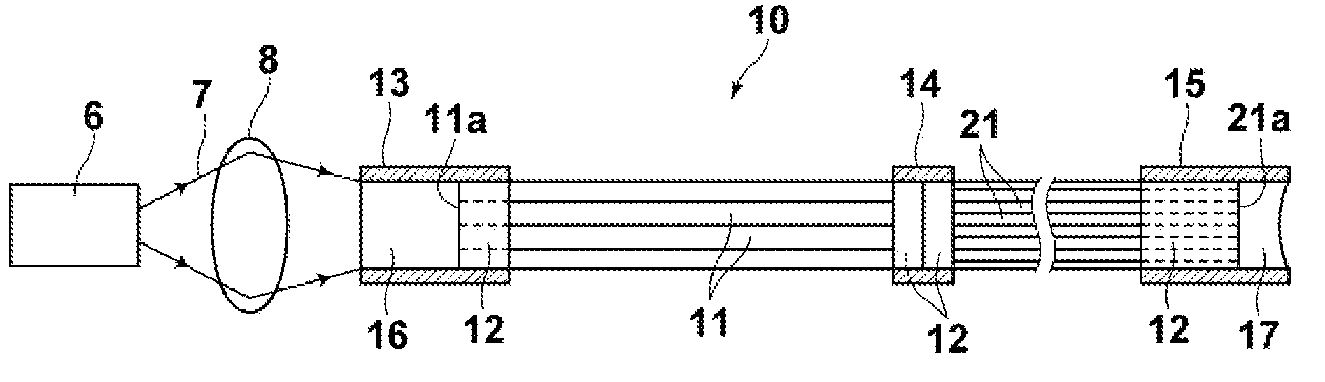
[0042]FIG. 1 is a side view that illustrates a light guide 10 for endoscopes according to the present invention. The light guide 10 for endoscopes is constituted by a plurality of bundled multi mode optical fibers 11 having comparatively large diameters, and a plurality of bundled multi mode optical fibers 21 having comparatively small diameters, connected to the multi mode optical fibers 11. A first end portion of the bundled multi mode optical fibers 11 (the left end portion in FIG. 1) and a second end portion of the bundled multi mode optical fibers 11 (the right end portion in FIG. 1) are housed in cylindrical connector housings 13 and 14, respectively, and fixed therein by filling adhesive 12. Similarly, a first end portion of the multi mode optical fibers 21 (the left end portion in FIG. 1) and a second end portion of the multi mode optical fibers 21 (the right end portion in FIG. 1) are housed in cylindrical connector housings 14 and 15, respectively, and fixed therein by fil...

second embodiment

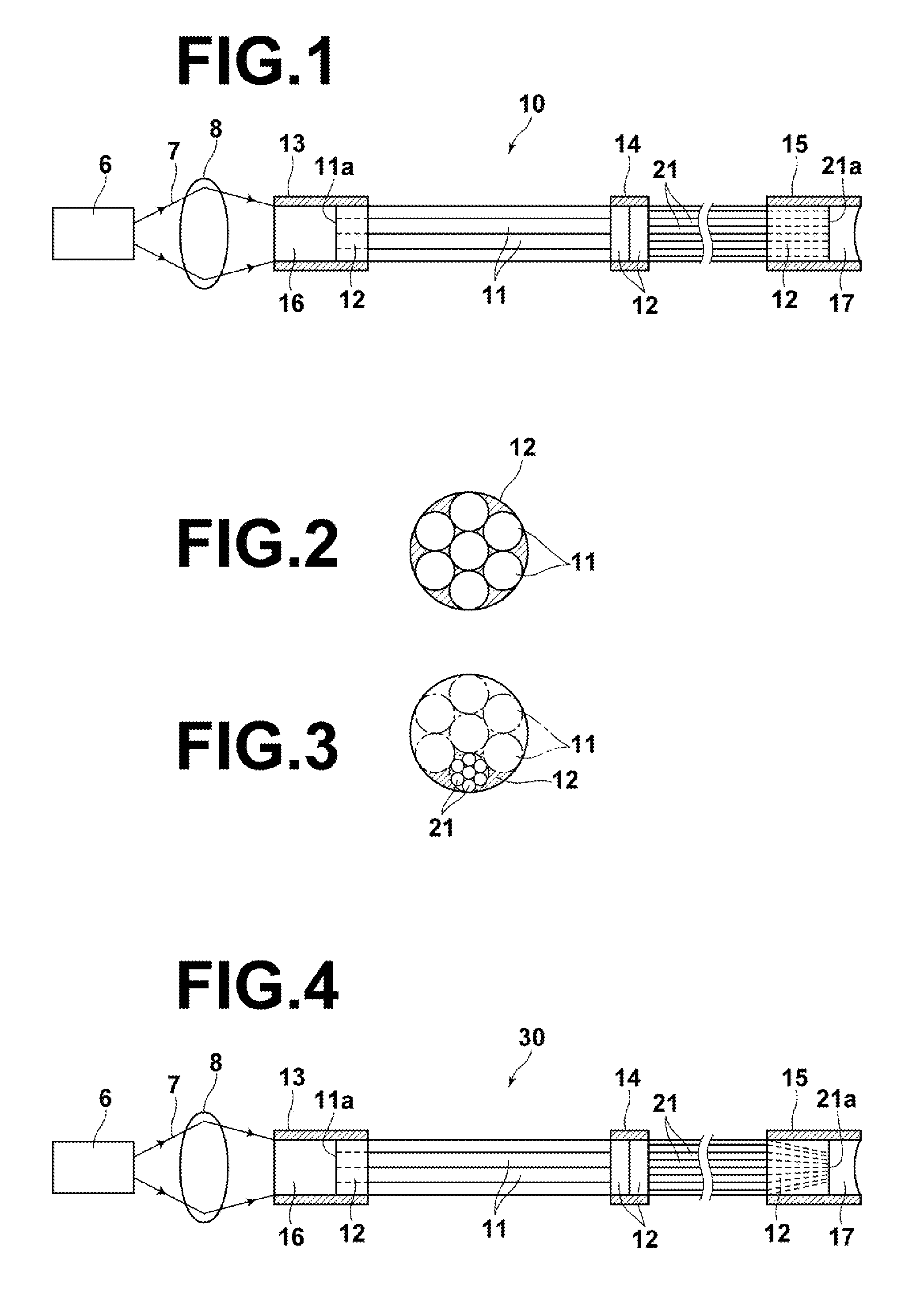
[0055]In the light guide for endoscopes 30 of the second embodiment as well, the portion in the vicinity of the light output end thereof is constituted by the comparatively small diameter multi mode optical fibers 21. Therefore, this portion can be flexed at smaller radii of curvature. On the other hand, the base portion of the light guide for endoscopes 30, at which flexibility is not required, is constituted by the comparatively large diameter multi mode optical fibers 11, thereby improving the durability thereof.

[0056]Further, the glass rod 16 is utilized at the light input portion of the light guide for endoscopes 30 in a similar manner to the light guide for endoscopes 10 of the first embodiment. Accordingly, the same advantageous effects which are obtained by the light guide for endoscopes 10 of the first embodiment are also obtained by the light guide for endoscopes 30 of the second embodiment.

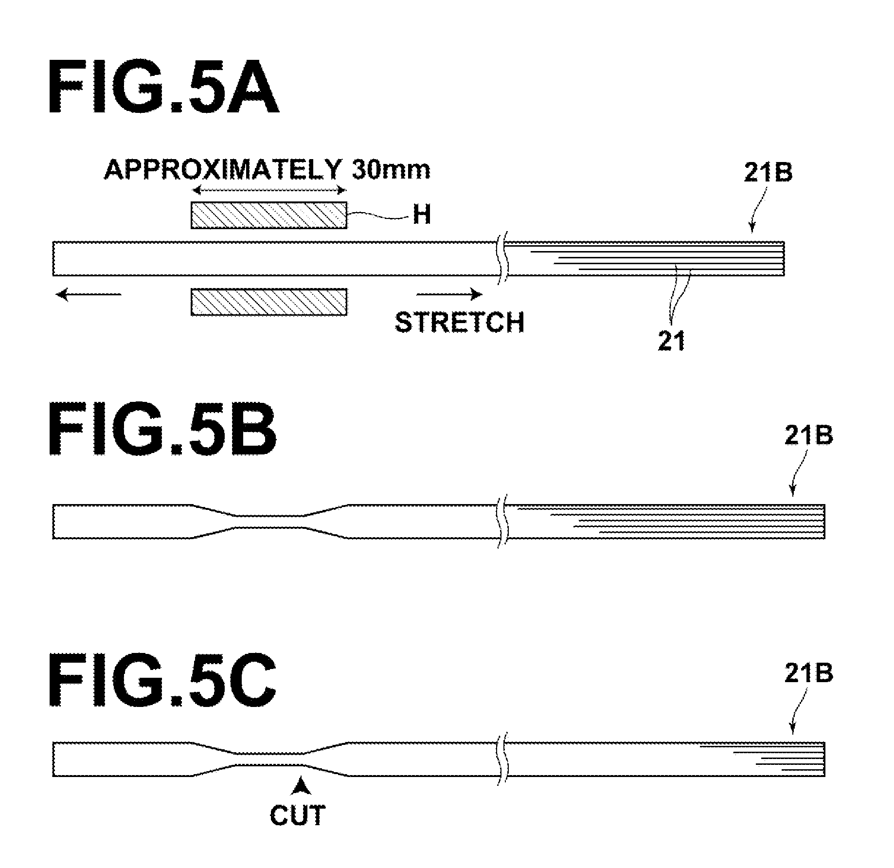
[0057]Next, a method for forming the light output portions of the plurality of mult...

third embodiment

[0059]In the light guide for endoscopes 40 of the third embodiment as well, the portion in the vicinity of the light output end thereof is constituted by the comparatively small diameter multi mode optical fibers 21. Therefore, this portion can be flexed at smaller radii of curvature. On the other hand, the base portion of the light guide for endoscopes 40, at which flexibility is not required, is constituted by the comparatively large diameter multi mode optical fibers 11, thereby improving the durability thereof.

[0060]In addition, in the light guide for endoscopes 40 of the third embodiment, the first end portion of the multi mode optical fibers 11, which is the light input portion where the illuminating light beam 7 enters, and the second end portion of the multi mode optical fibers 21, which is the light output portion where the illuminating light beam 7 is output, are both of tapered shapes. Therefore, the illuminating light beam enters the light input portion at a high utiliza...


PUM


Abstract

A light guide for endoscopes constituted by a plurality of bundled optical fibers is formed such that it is flexible at portions where flexibility is required, and such that the durability thereof is improved. The light guide for endoscopes is constituted by a plurality of bundled optical fibers, for propagating an illuminating light beam that enters from a light input end facet thereof to a light output end facet thereof, to emit the illuminating light beam onto a portion to be observed. The light guide includes: a plurality of comparatively large diameter optical fibers; and a plurality of comparatively small diameter optical fibers which are provided at the side of the light guide toward the light output end facet thereof. Each of the comparatively large diameter optical fibers is connected to a plurality of the comparatively small diameter optical fibers.

Description

BACKGROUND OF THE INVENTION[0001]1. Field of the Invention[0002]The present invention is related to a light guide for endoscopes, that is, a light guide that propagates light therethrough such that portions which are observed with an endoscope are illuminated.[0003]2. Description of the Related Art[0004]Conventionally, endoscopes are in wide use to observe and perform surgical procedures on portions within body cavities of humans. Flexible light guides for illuminating the observed portions of subjects are employed in these endoscopes. Note that in cases that surgical procedures are performed on portions, observation thereof is necessary. Therefore, portions on which surgical procedures are performed will also be referred to as “observed portions” in the present specification.[0005]At least a portion of this type of light guide is generally constituted by a plurality of thin multi mode optical fibers which are bundled, to impart flexibility thereto. Japanese Unexamined Patent Public...

Claims


Application Information

Patent Timeline
Patent Type & Authority Applications(United States)
IPC IPC(8): G02B6/06
CPCG02B23/2469A61B1/00165
Inventor SHIMOTSU, SHINICHI
Owner FUJIFILM CORP
Why Eureka
Try Eureka