Chair backrest device

a backrest and chair technology, applied in the field of chair backrest devices, can solve the problems of decreased durability, decreased and inability to achieve seating comfort, etc., and achieve the effect of decreasing the strength and rigidity of the backrest shell and seating comfor

Active Publication Date: 2010-01-07
OKAMURA CORP
View PDF16 Cites 123 Cited by
  • Summary
  • Abstract
  • Description
  • Claims
  • Application Information

AI Technical Summary

Benefits of technology

[0007]In view of the disadvantages, it is an object of the invention to provide a chair backrest device in which a backrest shell can flex effectively along the shape of the back of a person without decreasing strength and rigidity of the backrest shell, the device providing seating comfort.

Problems solved by technology

But the thickness of the backrest shell is almost equal, and the whole backrest shell is not effectively flexed rearward along the shape of the back, so that seating comfort is not obtained.
To overcome the disadvantage, the backrest shell can be made thinner for easier flexing, but the backrest shell decreases in strength and rigidity, so that durability is decreased and seating comfort is likely to get worse due to too much flexing.
However, in the support structure for the backrest shell, the right and left sides of the backrest shell supported by the backrest frame does not turn around a vertical axis, so that the whole backrest shell does not flex rearward effectively along the shape of the back of a person.

Method used


Image

  • Chair backrest device
  • Chair backrest device
  • Chair backrest device

Examples


Embodiment Construction

[0022]One embodiment of the present invention will be described with respect to drawings.

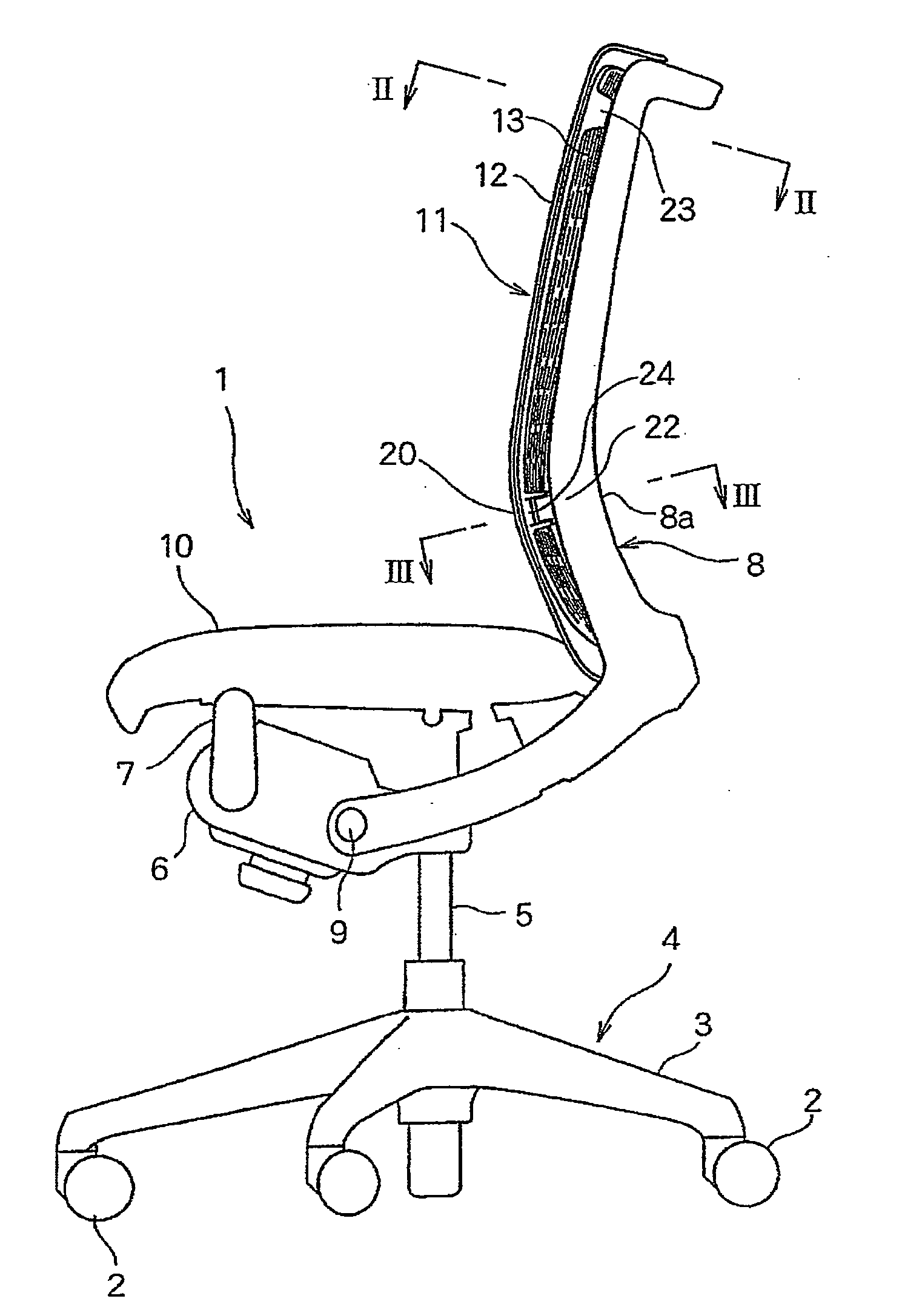
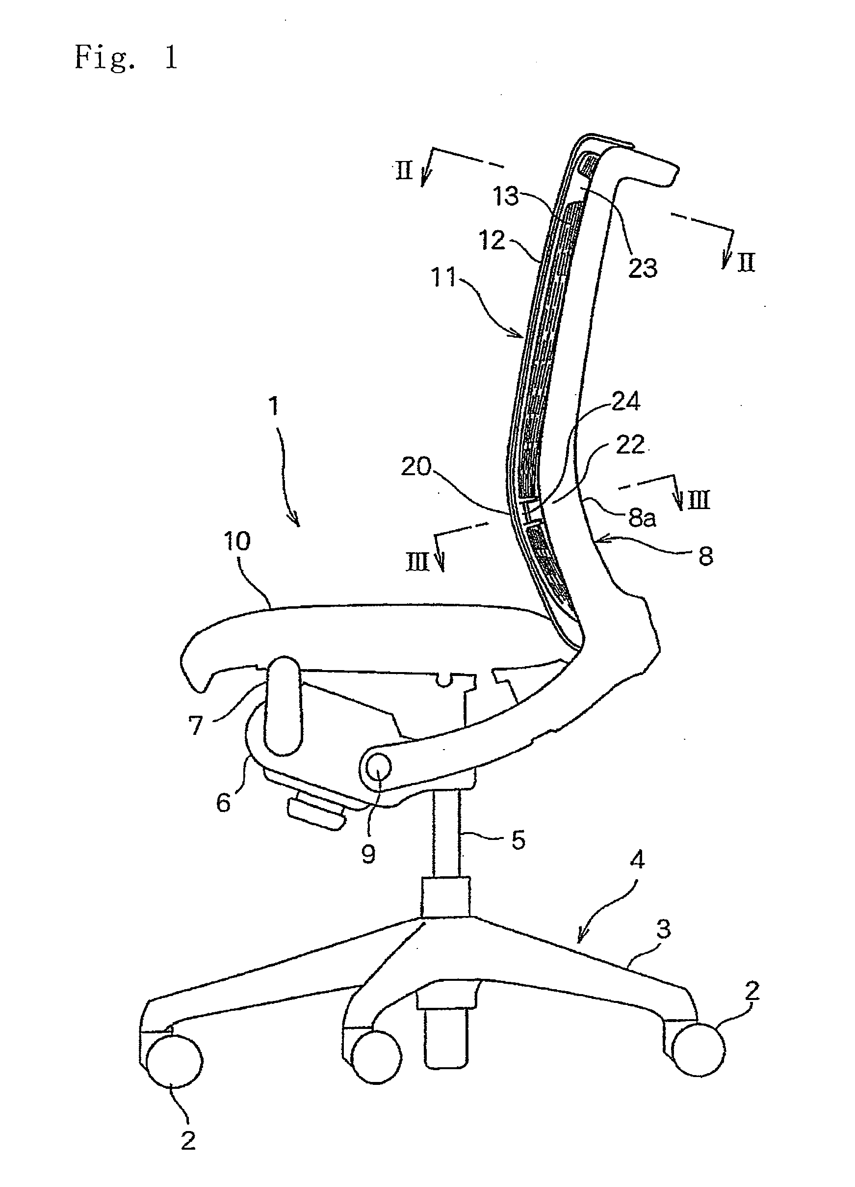
[0023]FIG. 1 is a side elevational view of a chair comprising a chair backrest device according to the present invention. FIG. 2 is an enlarged horizontal sectional end view taken along the line II-II in FIG. 1; and FIG. 3 is an enlarged horizontal sectional end view taken along the line III-III in FIG. 1.

[0024]A chair 1 comprises a leg unit 4 having five radially-extending legs 3 each of which has a caster 2 at the end; a post 5 standing at the center of the leg unit 4 and retractable with a gas spring (not shown); and a base 6 fixed at the upper end of the post 5.

[0025]A seat support frame 7 is mounted at the lower end to the front end of the base 6. To the base 6, the front ends of side frames 8a of a backrest frame 8 are pivotally mounted on a pivot shaft 9. The backrest frame 8 is always urged forward and downward by urging means (not shown) within the base 6.

[0026]A seat 10 is supported at...


PUM


Abstract

A backrest device for a chair, capable of, without a reduction in its strength and rigidity, effectively bending backward so as to follow the shape of the back of a person seated on the chair, providing the person with excellent sitting comfort. In the backrest device, a back board is supported by a backrest frame, and the back board has a flexible back stopper on the inner side of a back frame. The thickness of a vertical intermediate section of the back stopper is gradually increased from both left and right sections of the intermediate section toward the center such that the thickness is less in both left and right sections and is maximum at the center.

Description

BACKGROUND OF THE INVENTION[0001]The present invention relates to a chair backrest device comprising the flexible back support supporting the back of a sitting person in a backrest frame.[0002]Such a chair backrest device is disclosed, for example, in JP2002-125797A, JP2005-160558A, particularly in FIGS. 10-17, and JP2001-128785A.[0003]In the backrest shell of the backrest device in JP2002-125797A and JP2005-160558A, a number of openings are formed all over the backrest shell, which is flexed rearward when it is pressed by the back of a person. But the thickness of the backrest shell is almost equal, and the whole backrest shell is not effectively flexed rearward along the shape of the back, so that seating comfort is not obtained.[0004]To overcome the disadvantage, the backrest shell can be made thinner for easier flexing, but the backrest shell decreases in strength and rigidity, so that durability is decreased and seating comfort is likely to get worse due to too much flexing.[00...

Claims


Application Information

Patent Timeline
Patent Type & Authority Applications(United States)
IPC IPC(8): A47C7/02
CPCA47C7/40A47C7/282A47C31/023A47C7/445
Inventor MASUNAGA, HIROSHIIGARASHI, RYOODA, YOICHIRO
Owner OKAMURA CORP
Why Eureka
Try Eureka