Projection display device

a projection display and display device technology, applied in the direction of projectors, instruments, optics, etc., can solve the problems of deterioration of the projected image, large amount of heat generated by the light modulator and the polarizer,

Active Publication Date: 2010-03-04
SANYO ELECTRIC CO LTD
View PDF4 Cites 1 Cited by
  • Summary
  • Abstract
  • Description
  • Claims
  • Application Information

AI Technical Summary

Benefits of technology

[0016]According to the above arrangement, the air flowing in the space between the light modulator and the polarizer is deflected toward the polarizer. In this arrangement, even if the ...

Problems solved by technology

A large amount of heat is generated from the light modulator and the polarizers when light is passed through the light modulator and the polarizers.
In view of ...

Method used


Image

  • Projection display device
  • Projection display device
  • Projection display device

Examples


Embodiment Construction

[0028]In the following, an arrangement of a projector embodying the invention is described referring to the drawings.

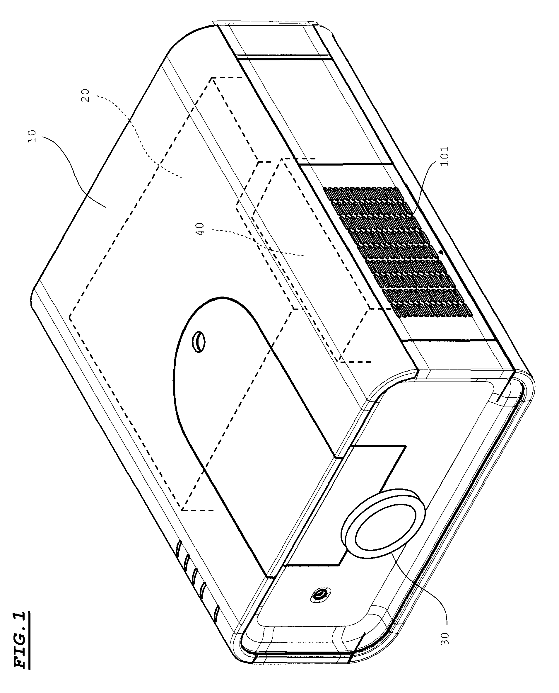
[0029]FIG. 1 is a diagram (external perspective view) showing an arrangement of a projector. Referring to FIG. 1, the projector includes a cabinet 10. The cabinet 10 has a substantially parallelepiped shape with a vertically small size and a transversely long size. An air inlet port 101 for drawing the external air into the cabinet 10 is formed in a side wall of the cabinet 10.

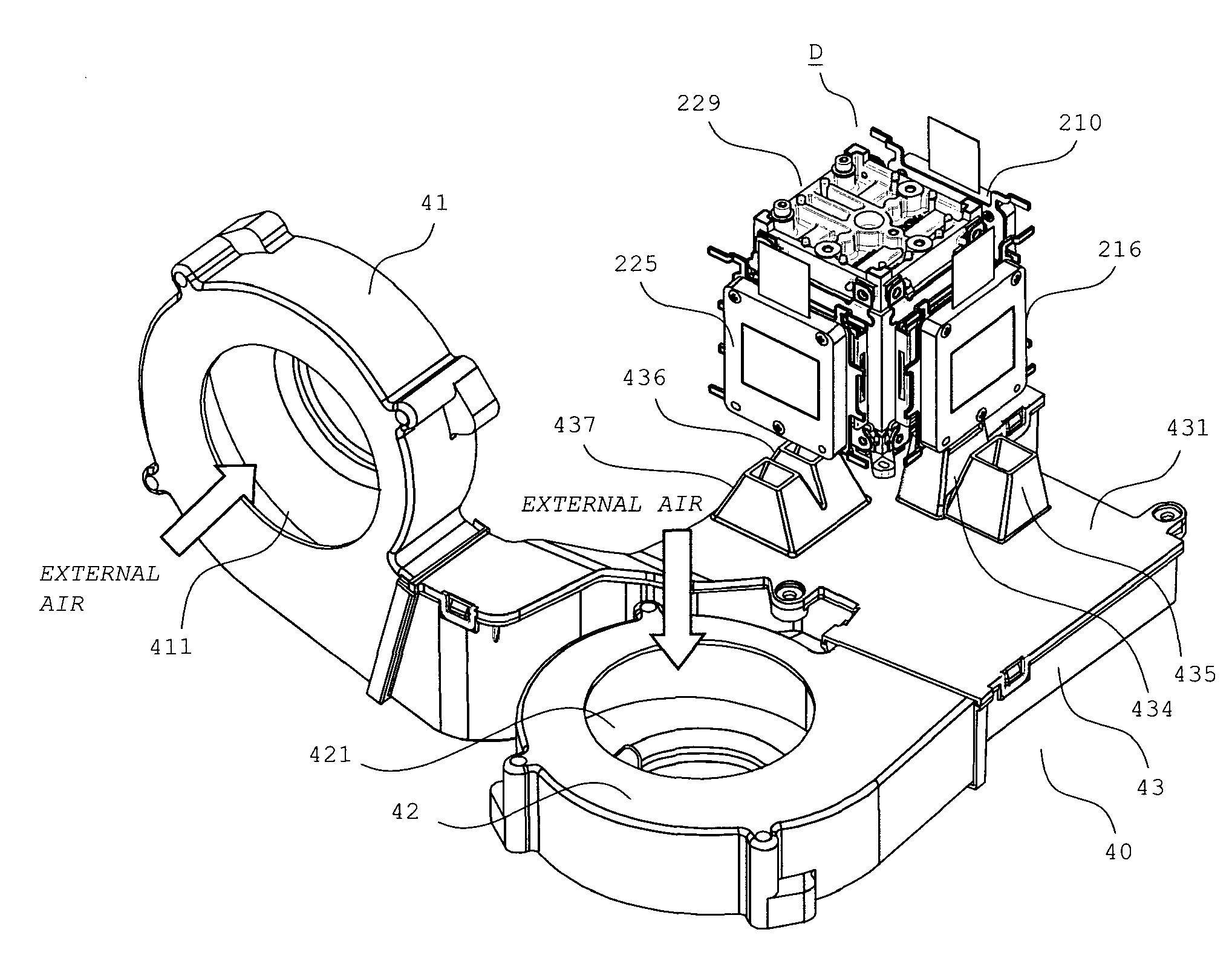
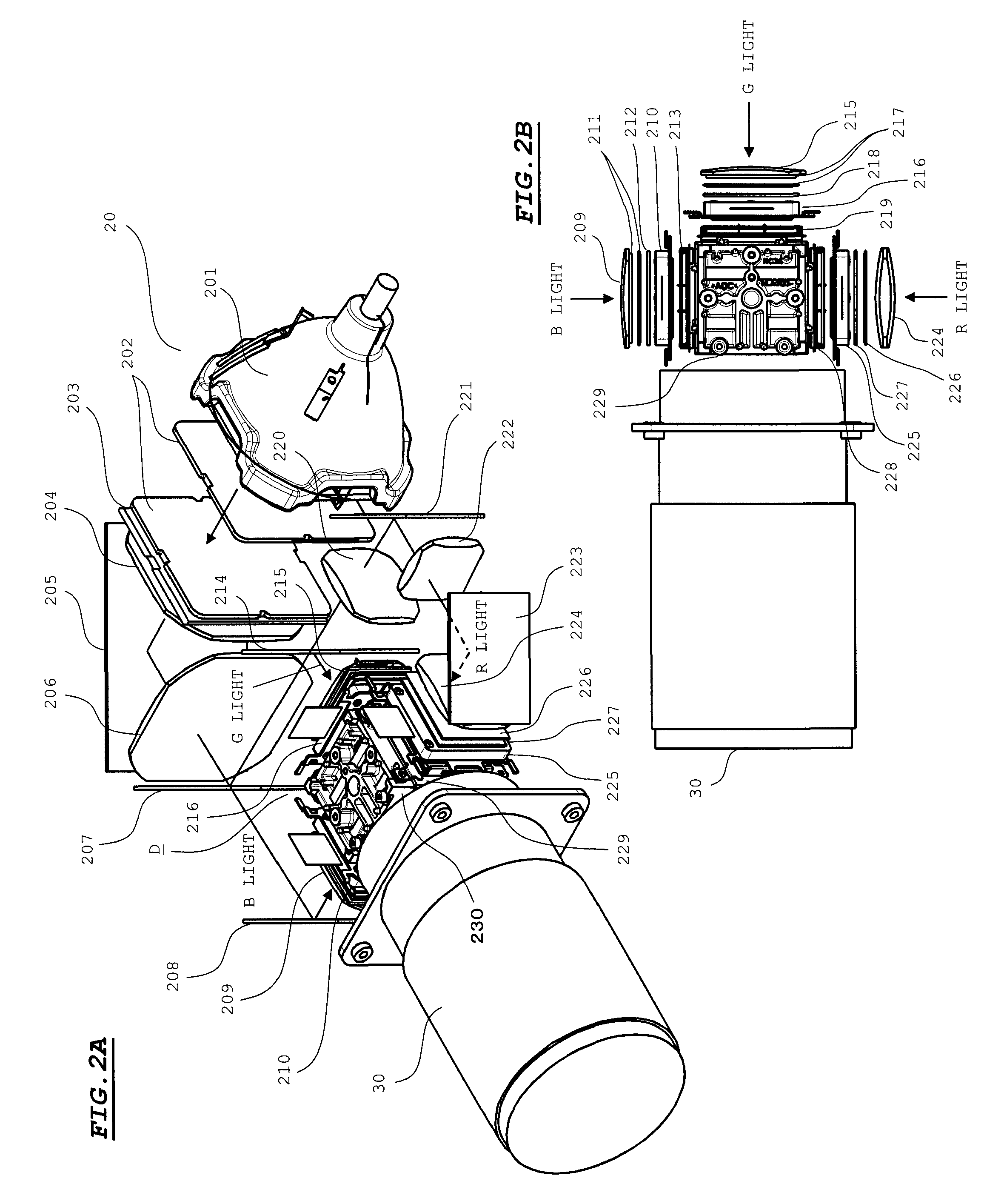
[0030]The cabinet 10 is internally provided with an optical engine 20, a projection lens 30, and a cooling device 40. The optical engine 20 generates image light modulated by an image signal. The projection lens 30 is mounted on the optical engine 20. A front portion of the projection lens 30 is exposed from a front wall of the cabinet 10. Image light generated by the optical engine 20 is projected onto a screen plane disposed in front of the projector through the projection lens 30. The cooling...


PUM


Abstract

A projection display device includes: a light modulator for modulating light from a light source; a polarizer disposed at a position facing the light modulator; a cooling section for allowing an air to flow in a space between the light modulator and the polarizer; and an air deflector for deflecting the air flowing in the space between the light modulator and the polarizer toward the polarizer.

Description

[0001]This application claims priority under 35 U.S.C. Section 119 of Japanese Patent Application No. 2008-225997 filed Sep. 3, 2008, entitled “PROJECTION DISPLAY DEVICE”. The disclosers of the above applications are incorporated herein by reference.BACKGROUND OF THE INVENTION[0002]1. Field of the Invention[0003]The present invention relates to a projection display device for projecting light modulated by an imager onto a projection plane.[0004]2. Description of the Related Art[0005]A projection display device (hereinafter, called as a “projector”) is constructed in such a manner that light from a light source is modulated by a light modulator constituted of an imager (such as a liquid crystal panel) to project the modulated light (hereinafter called as “image light”) onto a projection plane. Polarizers are disposed on an incident side and an exit side of the light modulator. A large amount of heat is generated from the light modulator and the polarizers when light is passed through...

Claims


Application Information

Patent Timeline
IPC IPC(8): G03B21/16
CPCG03B21/26
Inventor OKADA, HISASHIMINAMI, KAZUYANISHIHATA, YOSUKEMATSUYAMA, YUJI
Owner SANYO ELECTRIC CO LTD
Why Eureka
Try Eureka