Bonding equipment
- Summary
- Abstract
- Description
- Claims
- Application Information
AI Technical Summary
Benefits of technology
Problems solved by technology
Method used
Image
Examples
first embodiment
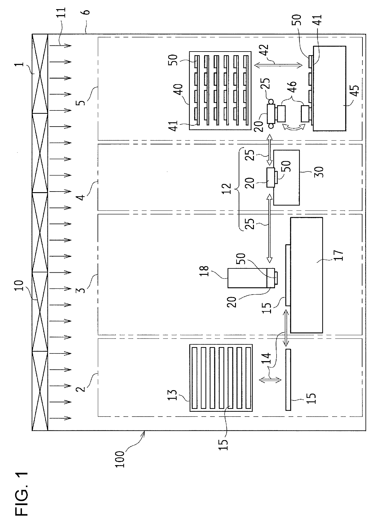
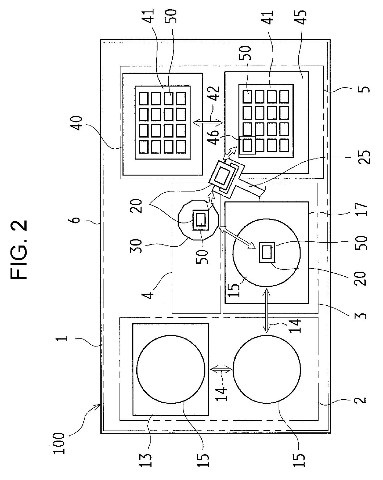
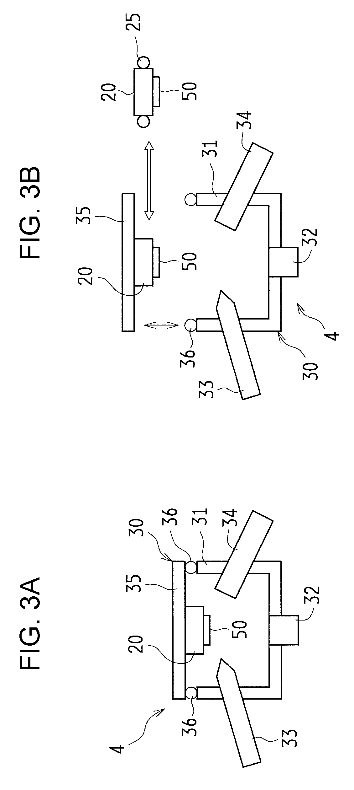
[0021]FIG. 1 illustrates bonding equipment 100 according to the first embodiment of the present disclosure and is a front view illustrating the bonding equipment 100. FIG. 2 is a top view illustrating the bonding equipment 100, and FIGS. 3A and 3B are cross-sectional views illustrating a configuration of a cleaning portion 4 in the bonding equipment 100. In addition, FIGS. 12A to 12D are cross-sectional views schematically illustrating a bonding state of a substrate and a chip.
[0022]Each of the drawings referred to in the following description is a schematic explanatory view illustrating a configuration of the bonding equipment 100 according to the present disclosure, for simplicity, a specific form such as a housing, a transfer portion, or the like will be omitted. In the cross-sectional view in FIGS. 3A and 3B or the like, the cleaning portion 4 in the bonding equipment 100 is schematically illustrated by a cross section, and in order to make the drawing easier to see, hatching il...
second embodiment
[0073]FIGS. 4 and 5 illustrate the bonding equipment 100 according to the second embodiment of the present disclosure. FIG. 4 is a front view illustrating the bonding equipment 100 and FIG. 5 is a top view illustrating the bonding equipment 100.
[0074]In the embodiment described below, since the basic configuration is common with the first embodiment, the common configuration is denoted by the same reference numerals as those in the first embodiment, and a detailed description thereof will be omitted.
[0075]In the first embodiment, the laminar flow source 1 is provided on the ceiling part, and each configuration member is disposed in the laminar flow of the downflow. On the other hand, the bonding equipment 100 according to the present embodiment has a characteristic in the laminar flow source 1, and each configuration member is disposed in a horizontal laminar flow 11h.
[0076]As illustrated in FIGS. 4 and 5, the laminar flow source 1 is disposed on one side of sides of the bonding eq...
third embodiment
[0079]FIGS. 6, 7A, and 7B illustrate the bonding equipment 100 according to the third embodiment of the present disclosure. FIG. 6 is a front view and FIGS. 7A and 7B are cross-sectional views illustrating the cleaning portion 4.
[0080]The bonding equipment 100 according to the third embodiment has a characteristic in a transfer method of the chip 50 and the cleaning chamber 30, as compared with the bonding equipment 100 according to the first embodiment. That is, in the first embodiment, the chip 50 is configured to be transferred and cleaned in a state of being chucked to the bonding head 20, but in the present embodiment, the chip 50 is configured to transferred and cleaned by itself. Such a configuration is suitable for a case where the chip 50 is relatively large, or a case where the non-electrode surface of the chip is smoothly polished and dust generation is small.
[0081]The bonding equipment 100 includes a transfer hand (a second transfer hand) 26 as the transfer mechanism 12....
PUM
 Abstract
Description
Claims
Application Information
 - R&D
- Intellectual Property
- Life Sciences
- Materials
- Tech Scout
- Unparalleled Data Quality
- Higher Quality Content
- 60% Fewer Hallucinations
Browse by: Latest US Patents, China's latest patents, Technical Efficacy Thesaurus, Application Domain, Technology Topic, Popular Technical Reports.
© 2025 PatSnap. All rights reserved.Legal|Privacy policy|Modern Slavery Act Transparency Statement|Sitemap|About US| Contact US: help@patsnap.com


