Rotary pump and brake device in which rotary pump is provided

a technology of rotary pump and brake device, which is applied in the direction of brake system, machine/engine, liquid fuel engine, etc., can solve the problems of excessive pressure of brake fluid, increased discharge pulsation, and increased sealing surface pressure, so as to increase the braking force

Inactive Publication Date: 2010-03-11
ADVICS CO LTD +1
View PDF6 Cites 11 Cited by
  • Summary
  • Abstract
  • Description
  • Claims
  • Application Information

AI Technical Summary

Benefits of technology

[0017]Making the seal element ring-shaped in this manner makes it possible to provide the scaling all the way around the central axis of rotation of the outer rotor and the inner rotor. This in turn makes it possible for the thin-walled portion to be provided on one side of the seal element in the radial direction and for the displaceable thin-walled portion to be formed easily.
[0018]It is preferable for the rotary pump that is described above to be used in a brake device that uses a high fluid pressure. Specifically, according to a sixth aspect of the present invention, a brake device is provided that includes brake fluid pressure generating elements, braking force generation elements, a main hydraulic conduit, and an auxiliary hydraulic conduit. The brake fluid pressure generating elements generate a brake fluid pressure based on a pedal...

Problems solved by technology

However, with the known seal structure that is described above, the seal surface pressure tends to increase, and the brake fluid pressure increases excessively within a closed portion among the plurality of chambers that is not continuous with either one of a suction port and a discharge port.
This creates a problem in that, when the brake fluid is discharged from the discharge port while the closed portion is continuous with the disch...

Method used


Image

  • Rotary pump and brake device in which rotary pump is provided
  • Rotary pump and brake device in which rotary pump is provided
  • Rotary pump and brake device in which rotary pump is provided

Examples


first embodiment

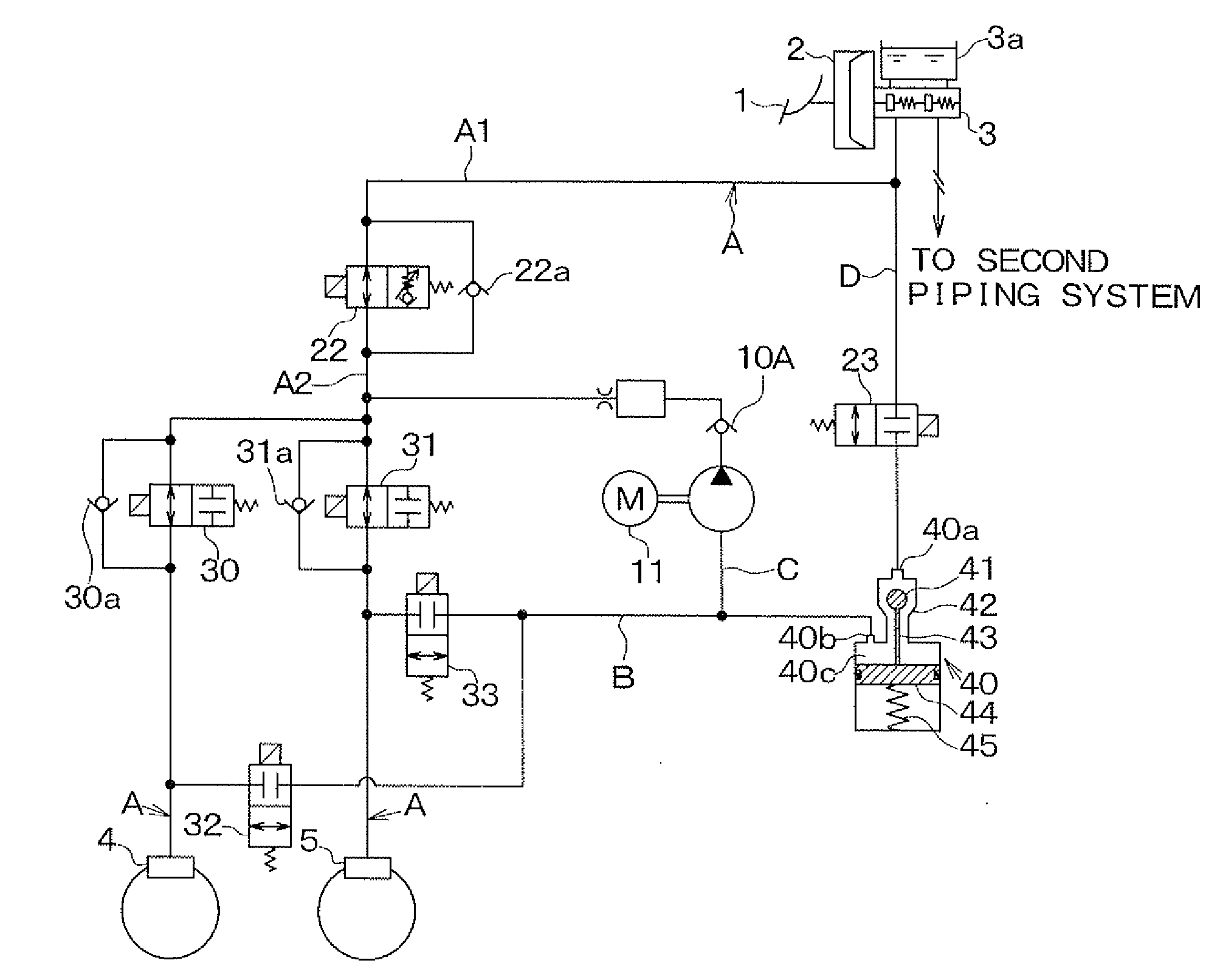
[0035]First, a basic configuration of a brake device will be explained based on FIG. 1. An example will be explained in which a brake device according to the present invention is used in a four-wheeled vehicle with front wheel drive, in which the hydraulic circuit is a diagonally-split brake system that is provided with separate piping systems for connecting the right front wheel and left rear wheel and connecting the left front wheel and right rear wheel, but the brake device can also be used with separate front and rear piping systems and the like.

[0036]As shown in FIG. 1, a brake pedal 1 is connected to a brake booster 2, and a brake pedal force or the like is multiplied by the brake booster 2.

[0037]The brake booster 2 includes a push rod or the like that transmits the multiplied pedal force to a master cylinder 3, and the push rod generates a master cylinder pressure by pressing on a master piston that is provided in the master cylinder 3. Note that the brake pedal 1, the brake ...

second embodiment

[0088]A second embodiment of the present invention will be explained. In the brake device in the present embodiment, the structure of the resin members 100b, 101b of the seal members 100, 101 in the rotary pump 10 is different from the structure in the first embodiment. In all other respects, the second embodiment is the same as the first embodiment, so only the portions that differ will be explained.

[0089]FIG. 5A is an enlarged front view of the resin member 100b in the seal member 100. FIG. 5B is an enlarged oblique view of the resin member 100b. FIG. 5C is an enlarged sectional view of the resin member 100b along a line D-D in FIG. 5A. Hereinafter, the structure of the resin members 100b, 101b according to the present embodiment will be explained in detail using FIGS. 5A to 5C. Note that in the present embodiment as well, the resin members 100b, 101b are mirror images of one another that symmetrically sandwich the outer rotor 51 and the inner rotor 52 between them.

[0090]As shown ...

third embodiment

[0092]A third embodiment of the present invention will be explained with reference to FIGS. 6A and 6B. In the brake device in the present embodiment, the structure of the resin members 100b, 101b of the seal members 100, 101 in the rotary pump 10 is different from the structure in the first embodiment. In all other respects, the second embodiment is the same as the first embodiment, so only the portions that differ will be explained.

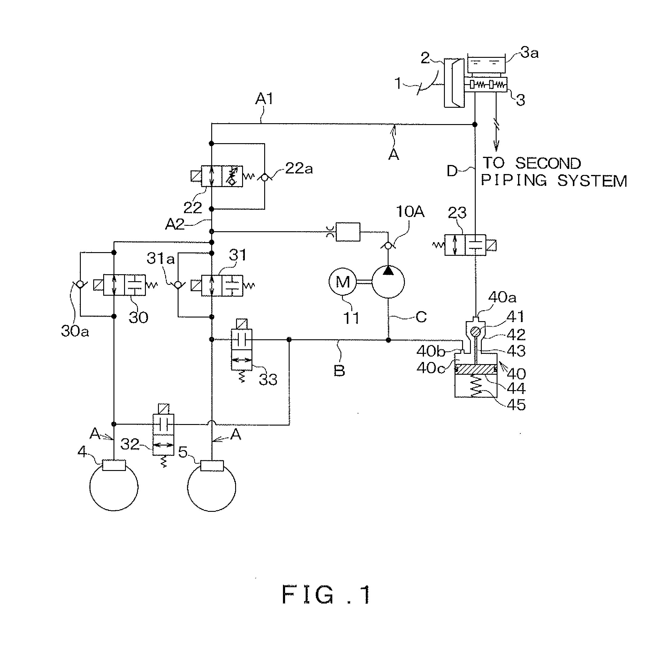
[0093]FIGS. 6A and 6B are schematic sectional views that show relationships among forces that act on individual locations of the resin members 100b, 101b. The cross sections correspond to the cross section along the line C-C in FIG. 2A.

[0094]As shown in FIGS. 6A and 6B, in the rotary pump 10 according to the present embodiment, counterbore portions (groove portions) 100h, 101h that reduce the thicknesses of the sealing portions 100e, 101e are provided in the sealing portions 100e, 101e on the opposite sides (rear face sides) from the end faces that face ...


PUM


Abstract

In an inner wall surface of a casing, grooves are formed that correspond to end faces of an outer rotor and an inner rotor, and seal members are disposed within the grooves, the seal members presses against the end faces of the outer rotor and the inner rotor. Inclined portions are provided in sealing portions of resin members of seal members, the sealing portions covering a closed portion. With this configuration, an internal pressure in the closed portion causes the inclined portions to separate from an outer rotor and an inner rotor when a brake fluid pressure within the closed portion increases to the point that the brake fluid is excessively compressed, releasing the brake fluid that is inside the closed portion. It is therefore possible to prevent the brake fluid pressure from increasing excessively within the closed portion.

Description

CROSS REFERENCE TO RELATED APPLICATION[0001]This application is based upon and claims the benefit of Japanese Patent Application No. 2008-231840 filed on Sep. 10, 2008, the content of which are incorporated herein by reference.BACKGROUND OF THE INVENTION[0002]1. Field of the Invention[0003]The present invention relates to a rotary pump that sucks and discharges a fluid and to a brake device in which the rotary pump is provided, the present invention being particularly suitable for application to an internal gear pump such as a trochoid pump or the like.[0004]2. Description of the Related Art[0005]An internal gear type of rotary pump, such as a trochoid pump or the like, is configured from an inner rotor that is provided with an external tooth portion on its outer circumference, an outer rotor that is provided with an internal tooth portion on its inner circumference, a casing that houses the inner rotor and the outer rotor, and the like. The inner rotor and the outer rotor are dispo...

Claims


Application Information

Patent Timeline
IPC IPC(8): B60T8/40F04C2/10
CPCB60T8/3655B60T8/4031B60T8/4872F04C15/0026F04C2/102F04C14/265F01C19/005
Inventor YAMAGUCHI, TAKAHIROSHINKAI, HIROYUKITAKAHASHI, TAKUTOUUCHIYAMA, KAZUNORIHAKAMADA, NAOKI
Owner ADVICS CO LTD
Why Eureka
Try Eureka