
Piezoelectric vibrating pieces and piezoelectric devices comprising same
a technology piezoelectric devices, which is applied in the direction of piezoelectric/electrostrictive device details, device material selection, etc., can solve the problems of ci value increasing disadvantageously, vibration leakage from the vibrating arms to the mounting regions and beyond, and the difficulty of etching with more miniaturized configurations of piezoelectric vibrating pieces. to achieve the effect of reducing vibration leakage and preventing ci valu
- Summary
- Abstract
- Description
- Claims
- Application Information
AI Technical Summary
Benefits of technology
Problems solved by technology
Method used
Image

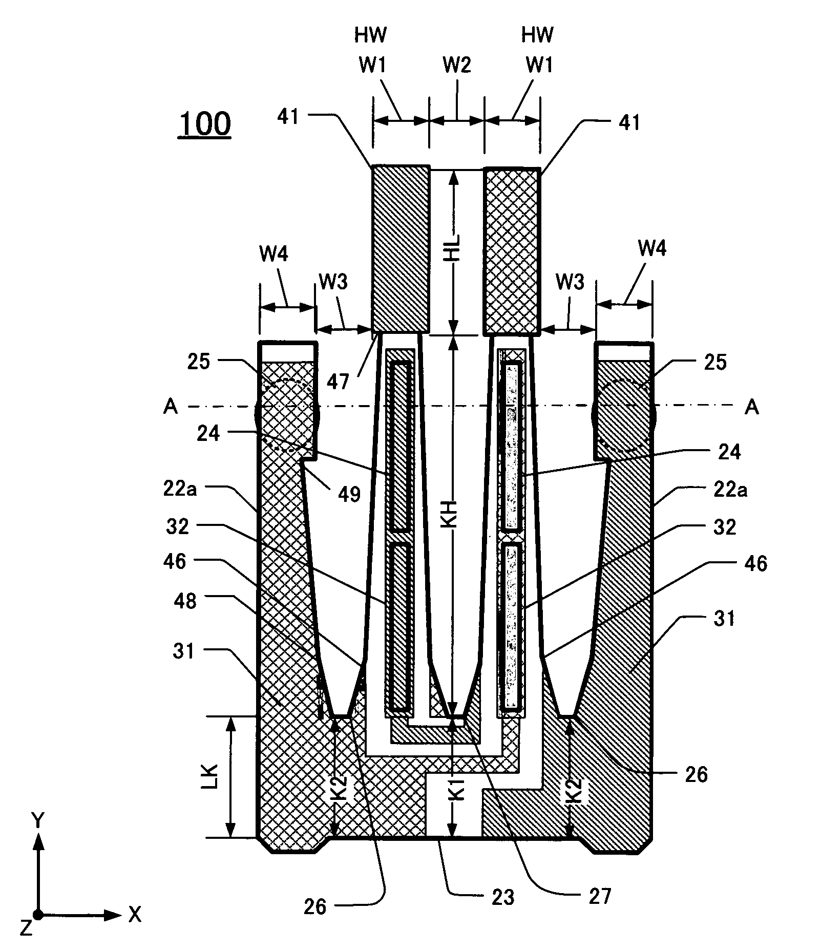
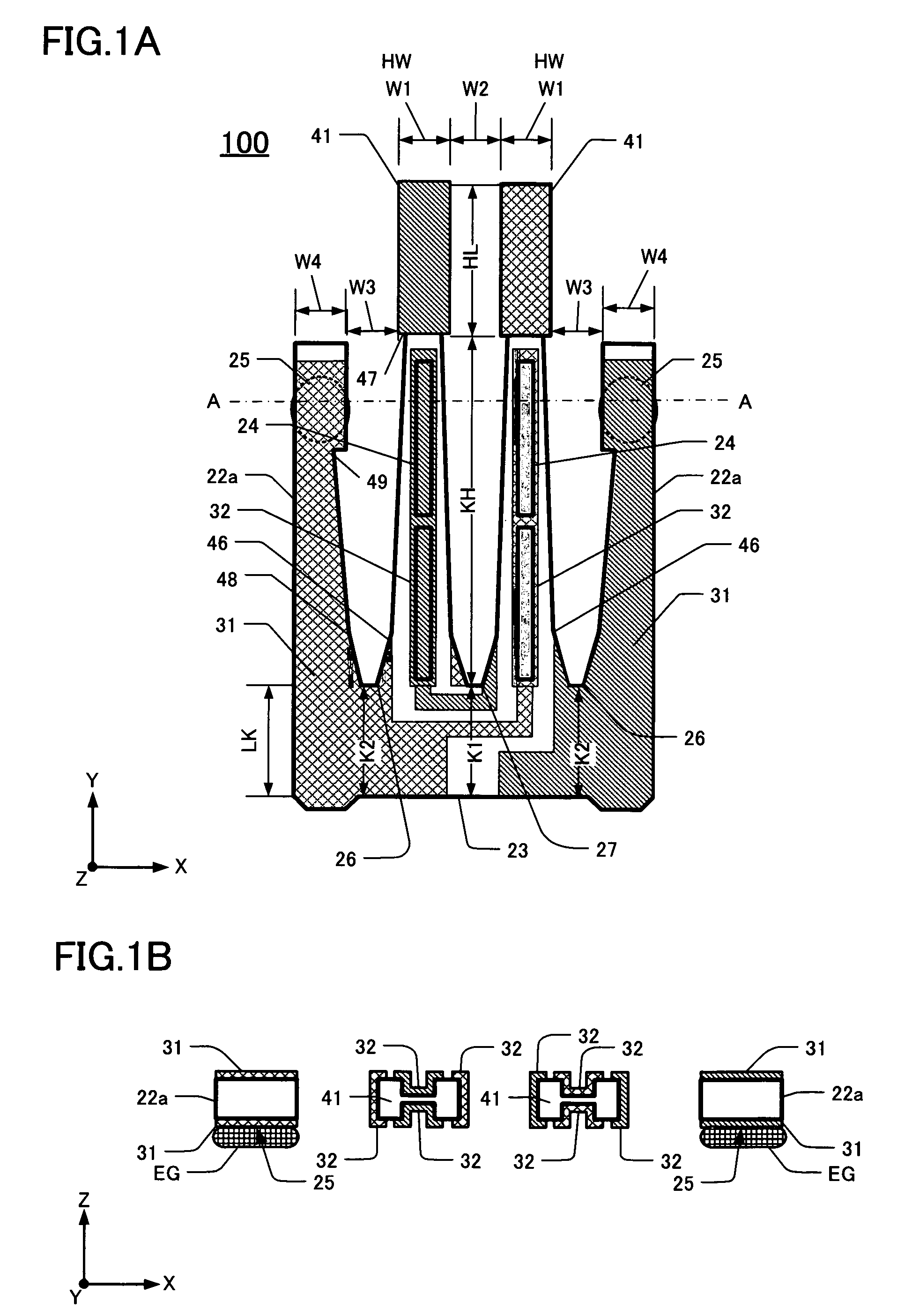
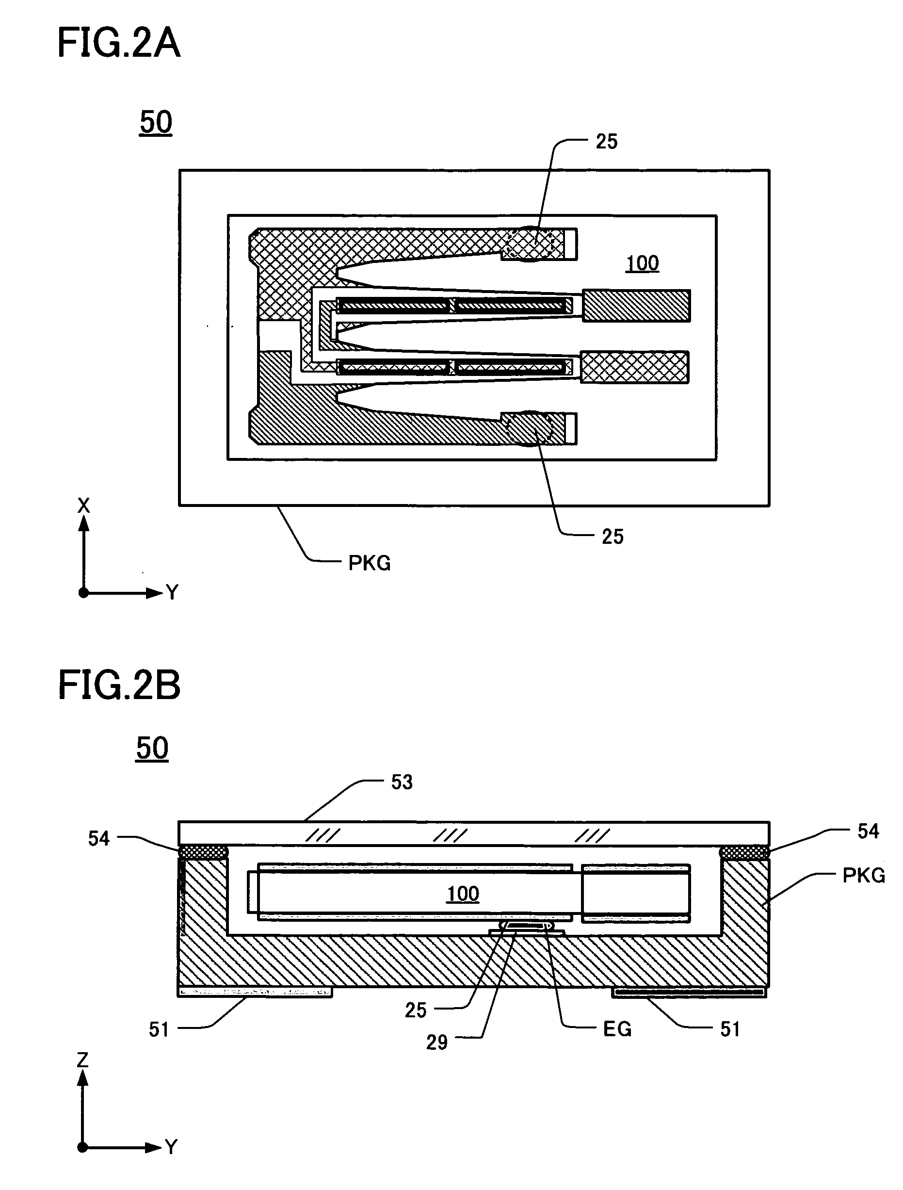
Examples
second embodiment
[0058]FIG. 3 is a plan view of a second embodiment of the tuning-fork type crystal vibrating piece 110, comprising a pair of vibrating arms 42 and a pair of supporting arms 22b. Except for the configuration of the vibrating arms 42 and supporting arms 22b of this embodiment 110, other components thereof are similar to corresponding components in the first embodiment and are not described further. Also, the electrodes are not shown in FIG. 3 (or described below) to facilitate clarity.
[0059]In FIG. 3 the root portions of the vibrating arms 42 extending upward (Y-direction) from the base 23 are wider in the X-direction than in FIG. 1A. The vibrating arms 42 extend “upward” in the Y-direction from the base 23 with an initial configuration in which they progressively narrow with increasing distance in the Y-direction from their respective root portions. A first constriction (or first “width”) 46 is located just distally of the root portions. From the first constriction 46 the vibrating a...
third embodiment
[0068]FIG. 5 is a plan view of a tuning-fork type crystal vibrating piece 120 according to a third embodiment. The vibrating arms 43 of this embodiment exhibit improved CI stability. Except for the description of the vibrating arms 43 of this embodiment, descriptions of other components and features of the crystal vibrating piece 120 are not provided because the other components and features are as described above in the first embodiment. Also, the electrodes are not described or shown to facilitate clarity of features actually shown.
[0069]Similar to the first embodiment, in the embodiment of FIG. 5 each vibrating arm 43 extends in the Y-direction (upward in the figure) from the base 23 while progressively narrowing to the first constriction (first “width”) 46. From the first constriction 46 each vibrating arm 43 progressively narrows further, with increasing distance along the Y-direction, to the second constriction (second “width”) 47 located near the distal end of the vibrating a...
fourth embodiment
[0072]This embodiment is shown in FIG. 6, which is a plan view of the tuning-fork type crystal vibrating piece 130 comprising a pair of vibrating arms 22c. Except for the following description of the vibrating arms 22c, descriptions of other components and features of the crystal vibrating piece 130 are not provided because the other components and features are as described above in the first embodiment. Also, the electrodes are not described or shown to facilitate clarity of features actually shown.
[0073]Each vibrating arm 41 of the fourth embodiment extends upward (Y-direction) from the base 23 parallel to each other. From the root portions 26, 27, the width of each vibrating arm 41 progressively decreases with increasing distance (Y-direction) from the base 23, up to the first constriction (first “width”) 46. With increasing distance (Y-direction) from the first constriction 46, the width of each vibrating arm 41 progressively decreases further, up to the second constriction (sec...
PUM
 Abstract
Description
Claims
Application Information