Piezoelectric vibrating devices having bisymmetric vibrating arms and supporting arms, and devices comprising same

a technology of piezoelectric vibrating elements and supporting arms, which is applied in the direction of piezoelectric/electrostrictive device details, device material selection, etc., can solve the problems of ci value increasing disadvantageously, vibration leakage from the vibrating arms to the mounting regions and beyond, and may be more difficult to perform etching with more miniaturized configurations of piezoelectric vibrating pieces. , to achieve the effect of reducing vibration leakage and preventing ci valu

Inactive Publication Date: 2012-05-08
NIHON DEMPA KOGYO CO LTD
View PDF19 Cites 14 Cited by
  • Summary
  • Abstract
  • Description
  • Claims
  • Application Information

AI Technical Summary

Benefits of technology

[0008]Various aspects of the invention include piezoelectric vibrating pieces and piezoelectric devices comprising same. According to a first aspect, piezoelectric vibrating pieces are provided, of which an embodiment comprises a base having a first end edge, an opposing second end edge, and side edges extending from the first end edge to the second end edge. A pair of vibrating arms extends from the first end edge of the base in a designated longitudinal direction (e.g., Y-direction). A respective supporting arm extends from each side edge of the base, outboard of the vibrating arms, in the designated longitudinal direction. Each supporting arm has a distal-end region and at least one mounting region in the distal-end region. A vibrating-root portion is situated between the vibrating arms, and respective supporting-root portions are situated at the first end edge of the base between each vibrating arm and respective supporting arm. Each supporting arm has a longitudinal edge extending from the respective supporting root portion to the mounting region, and each vibrating arm has a longitudinal edge extending opposite the longitudinal edge of the respective supporting arm. The longitudinal edges extend in a symmetrical manner relative to a respective centerline extending in the designated longitudinal direction between the respective vibrating arm and supporting arm. As a result of this symmetry about the centerlines the supporting arms and vibrating arms have balanced configurations that prevent increases in CI and reduce vibration leakage.
[0009]The piezoelectric vibrating piece desirably includes a vibrating root portion situated at the first end edge of the base between the vibrating arms. In this configuration, the distance (e.g., in the Y-direction or longitudinal direction) from the second end edge of the base to the vibrating root portion is substantially equal to the distance in the designated longitudinal direction from the second end edge of the base to each of the supporting root portions. When such a configuration is being fabricated, the flow of wet-etchant between and around the vibrating arms and supporting arms is substantially uniform so that balanced (substantially equal rates of) etching can be achieved in these areas. Achievement of these benefits may be enhanced by configuring the supporting-root portions and the vibrating-root portion with substantially similar plan profiles.
[0012]Another embodiment of a piezoelectric vibrating piece comprises a base, a pair of vibrating arms, and a pair of supporting arms. The vibrating arms extend from the first end edge of the base in a designated longitudinal direction (e.g., Y-direction). A respective supporting arm extends from each side edge of the base, outboard of the vibrating arms, in the designated longitudinal direction. Each supporting arm has a proximal portion at the respective side edge of the base, a distal-end region, and at least one mounting region in the distal end. Each supporting arm progressively narrows in the designated longitudinal direction from the proximal portion to the respective mounting region. These embodiments inhibit reduced vibration leakage from the vibrating arms through the base and through a base plate of a package. For example, vibrations are not readily conducted from the vibrating arms to the mounting regions and beyond.
[0016]In yet other embodiments, each vibrating arm progressively narrows in the designated longitudinal direction from the root portion to a first width and further narrows from the first width to a second width. From the second width to the distal end, each vibrating arm has a width greater than the second width. Such a configuration of the vibrating arms enhances their oscillation and achieves a stable oscillation frequency.
[0017]In another embodiment, each vibrating arm progressively narrows in the designated longitudinal direction from the root portion to a constriction. Then, each vibrating arm progressively widens in the designated longitudinal direction from the constriction to the distal end. Such a configuration of the vibrating arms enhances their oscillation and achieves a stable oscillation frequency.

Problems solved by technology

Not sufficiently preventing oscillation leakage allows the CI value to increase disadvantageously.
Also, etching may be more difficult to perform with more miniaturized configurations of piezoelectric vibrating pieces due to anisotropy of the crystal material from which they are made.
For example, vibrations are not readily conducted from the vibrating arms to the mounting regions and beyond.

Method used


Image

  • Piezoelectric vibrating devices having bisymmetric vibrating arms and supporting arms, and devices comprising same
  • Piezoelectric vibrating devices having bisymmetric vibrating arms and supporting arms, and devices comprising same
  • Piezoelectric vibrating devices having bisymmetric vibrating arms and supporting arms, and devices comprising same

Examples


second embodiment

[0058]FIG. 3 is a plan view of a second embodiment of the tuning-fork type crystal vibrating piece 110, comprising a pair of vibrating arms 42 and a pair of supporting arms 22b. Except for the configuration of the vibrating arms 42 and supporting arms 22b of this embodiment 110, other components thereof are similar to corresponding components in the first embodiment and are not described further. Also, the electrodes are not shown in FIG. 3 (or described below) to facilitate clarity.

[0059]In FIG. 3 the root portions of the vibrating arms 42 extending upward (Y-direction) from the base 23 are wider in the X-direction than in FIG. 1A. The vibrating arms 42 extend “upward” in the Y-direction from the base 23 with an initial configuration in which they progressively narrow with increasing distance in the Y-direction from their respective root portions. A first constriction (or first “width”) 46 is located just distally of the root portions. From the first constriction 46 the vibrating a...

third embodiment

[0068]FIG. 5 is a plan view of a tuning-fork type crystal vibrating piece 120 according to a third embodiment. The vibrating arms 43 of this embodiment exhibit improved CI stability. Except for the description of the vibrating arms 43 of this embodiment, descriptions of other components and features of the crystal vibrating piece 120 are not provided because the other components and features are as described above in the first embodiment. Also, the electrodes are not described or shown to facilitate clarity of features actually shown.

[0069]Similar to the first embodiment, in the embodiment of FIG. 5 each vibrating arm 43 extends in the Y-direction (upward in the figure) from the base 23 while progressively narrowing to the first constriction (first “width”) 46. From the first constriction 46 each vibrating arm 43 progressively narrows further, with increasing distance along the Y-direction, to the second constriction (second “width”) 47 located near the distal end of the vibrating a...

fourth embodiment

[0072]This embodiment is shown in FIG. 6, which is a plan view of the tuning-fork type crystal vibrating piece 130 comprising a pair of vibrating arms 22c. Except for the following description of the vibrating arms 22c, descriptions of other components and features of the crystal vibrating piece 130 are not provided because the other components and features are as described above in the first embodiment. Also, the electrodes are not described or shown to facilitate clarity of features actually shown.

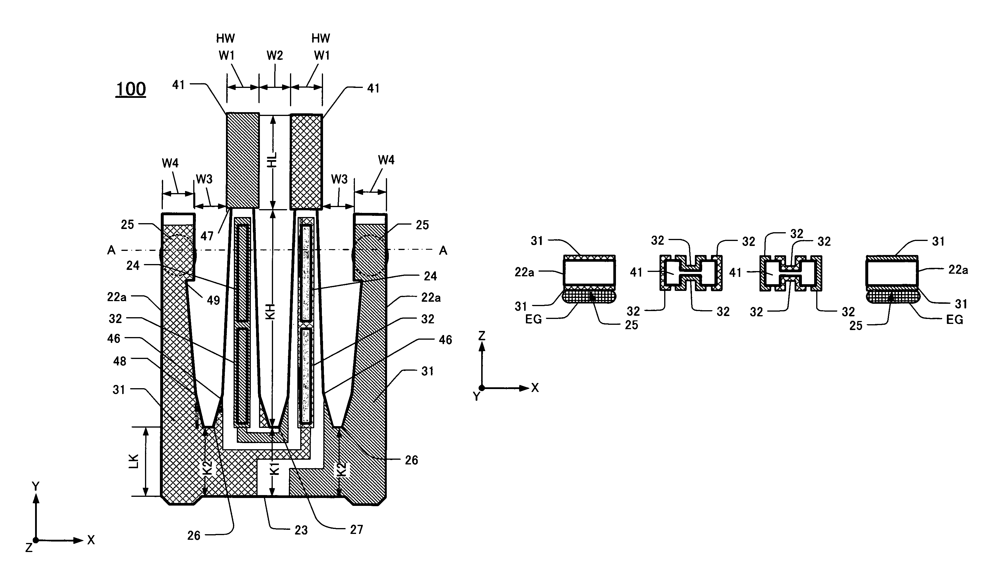
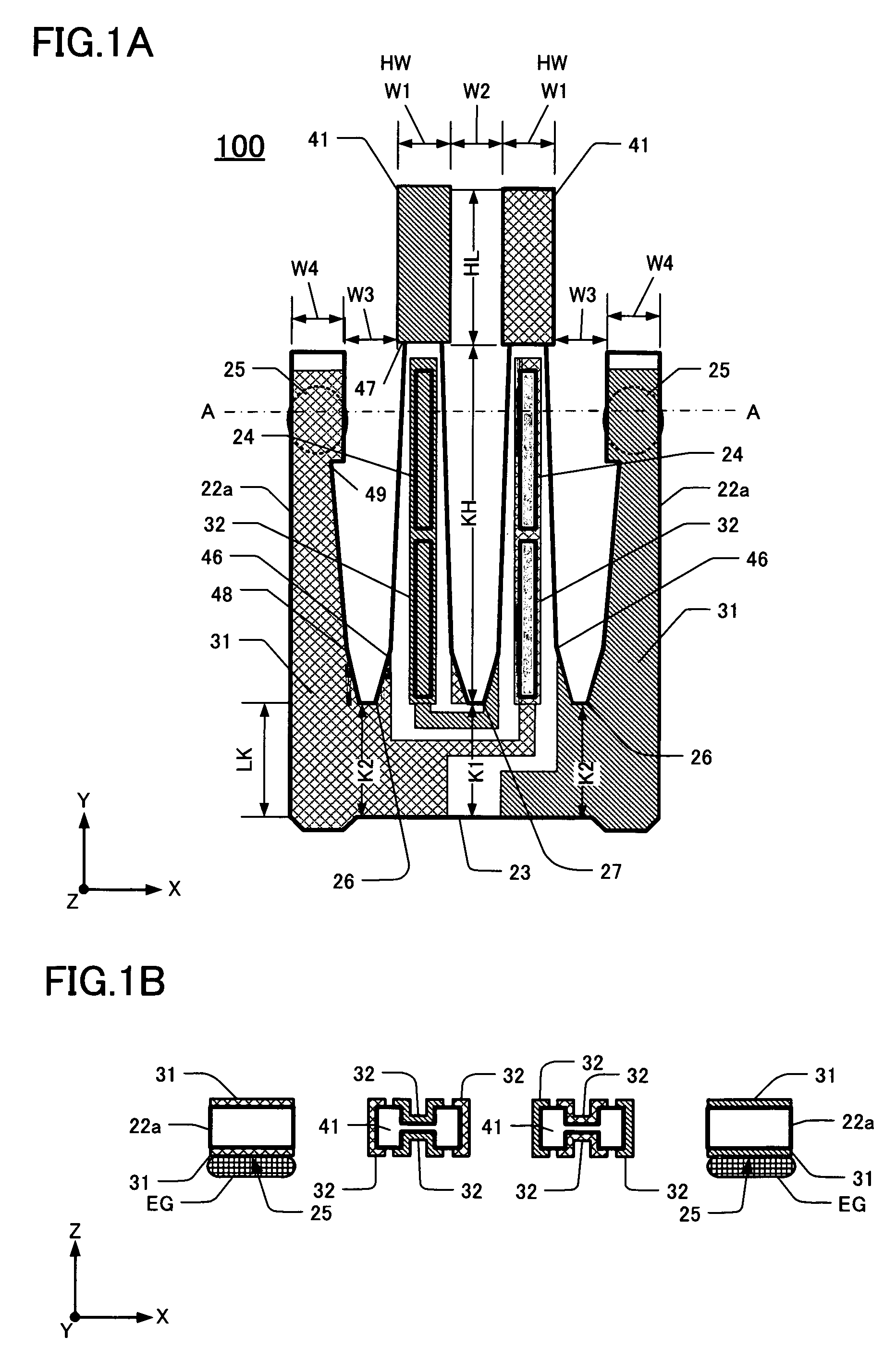
[0073]Each vibrating arm 41 of the fourth embodiment extends upward (Y-direction) from the base 23 parallel to each other. From the root portions 26, 27, the width of each vibrating arm 41 progressively decreases with increasing distance (Y-direction) from the base 23, up to the first constriction (first “width”) 46. With increasing distance (Y-direction) from the first constriction 46, the width of each vibrating arm 41 progressively decreases further, up to the second constriction (sec...


PUM


Abstract

An exemplary tuning-fork type piezoelectric vibrating piece has at least a pair of vibrating arms extending from one end of a base portion in a certain longitudinal direction (e.g., Y-direction). Supporting arms extend from respective side edges of the base, outboard of the vibrating arms in the certain direction. The supporting arms have respective mounting regions near their distal tips. Each supporting arm progressively narrows from its proximal end, coupled to the respective side edge of the base, to its respective mounting region. The progressive narrowing can be via one or more constrictions along the length of the supporting arm.

Description

CROSS-REFERENCE TO RELATED APPLICATION[0001]This application claims priority to and the benefit of Japan Patent Application No. 2008-251181, filed on Sep. 29, 2008, in the Japan Patent Office, the disclosure of which is incorporated herein by reference in its entirety.FIELD[0002]This disclosure pertains to, inter alia, methods for manufacturing tuning-fork type piezoelectric vibrating elements comprising supporting arms.DESCRIPTION OF THE RELATED ART[0003]Various types of clocks, home electric appliances, consumer electronics, and various types of commercial / industrial electrical apparatus such as information / communication devices and Office-Automation devices utilize at least one oscillator. These oscillators typically are manufactured by packaging a piezoelectric resonator, a piezoelectric vibrating piece, or an IC chip as a clock source for addition to and use by an electronic circuit of the apparatus. In other apparatus, piezoelectric timing devices such as real-time clock modul...

Claims


Application Information

Patent Timeline
Patent Type & Authority Patents(United States)
IPC IPC(8): H03H9/25H01L41/04H01L41/09H01L41/18H01L41/22H01L41/23H01L41/332H03H9/19H03H9/215
CPCH03H9/1021H03H9/215
Inventor IWAI, HIROKI
Owner NIHON DEMPA KOGYO CO LTD
Why Eureka
Try Eureka