

Yankee cylinder for paper producing machine
a paper producing machine and cylinder technology, applied in the direction of lighting and heating equipment, duplicating/marking methods, washing machines, etc., can solve the problems of poor performance and considerable thermal inertia, and achieve the effect of simple and safe construction system
- Summary
- Abstract
- Description
- Claims
- Application Information
AI Technical Summary
Benefits of technology
Problems solved by technology
Method used
Image

Examples
Embodiment Construction
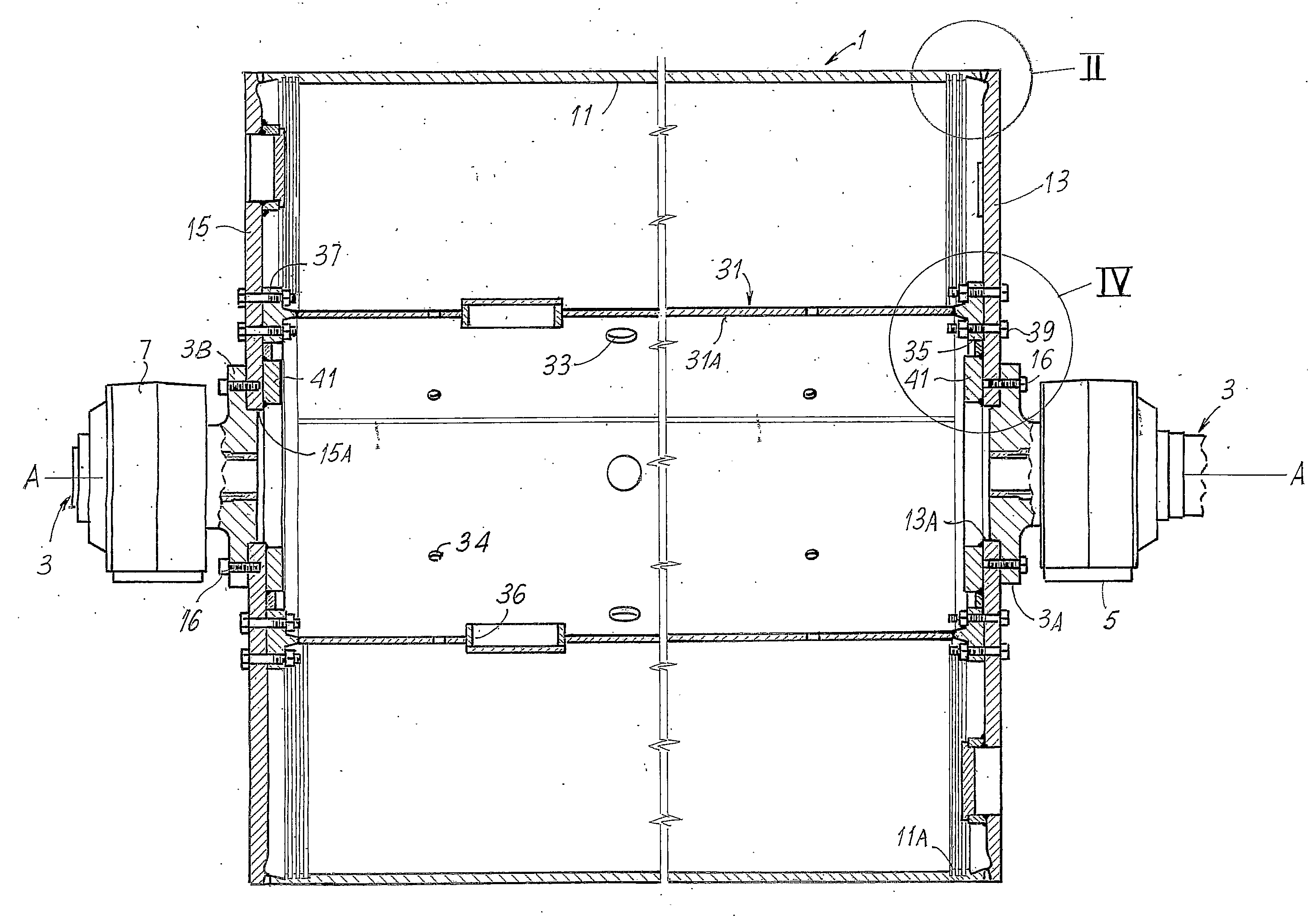
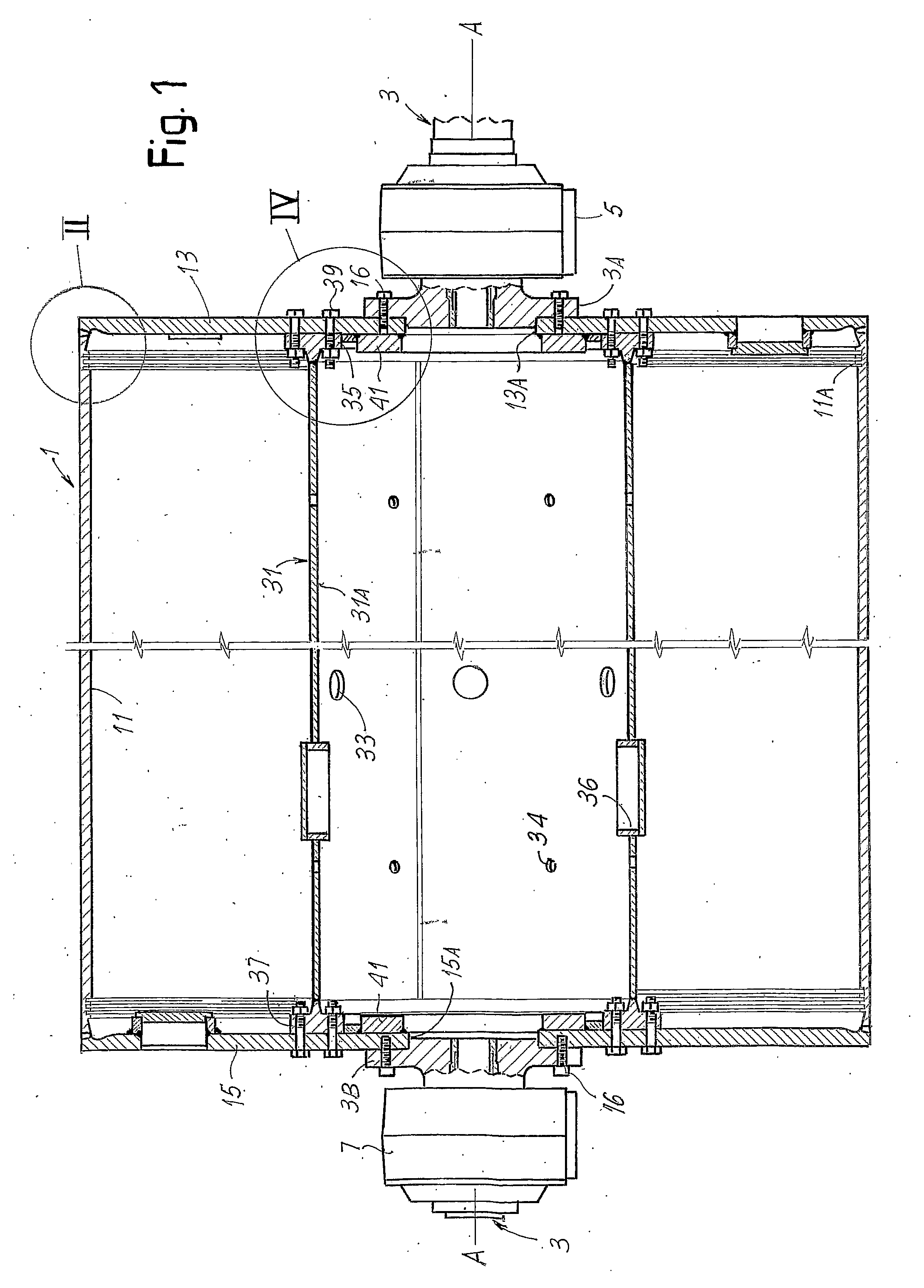
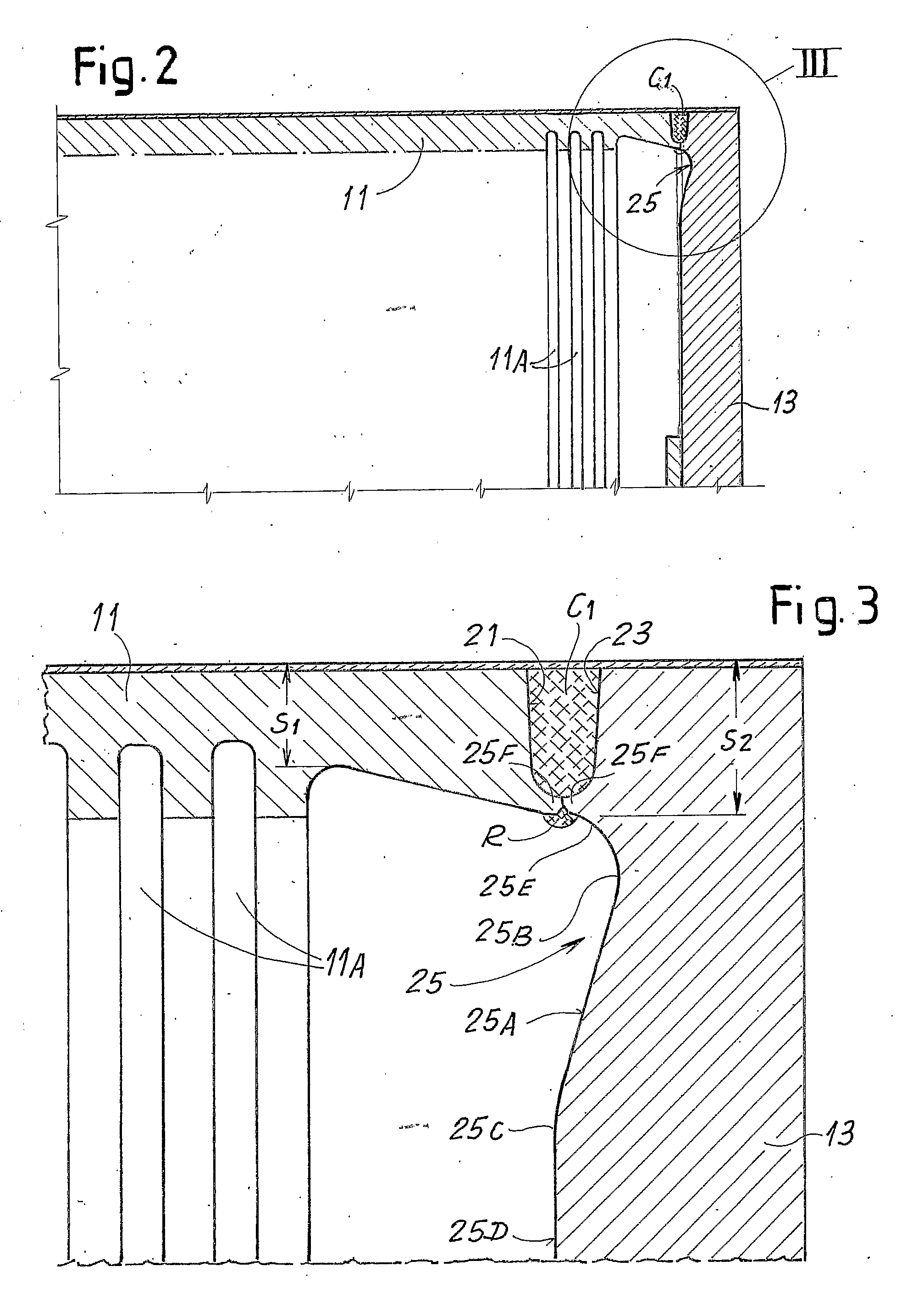
[0027]With initial reference to FIGS. 1 to 5 a first configuration of the Yankee cylinder according to the invention will be described below. In FIG. 1 the composition of the Yankee cylinder is shown in a longitudinal section containing the rotation axis A-A of the cylinder itself. The cylinder includes a main body 1 and two journals 3 through which the cylinder is supported by means of roller bearings 5 and 7. Through journals 3 a thermal carrier fluid is circulated, usually steam, that fills the internal chamber of the Yankee cylinder. The chamber is constructed in body 1 of the cylinder, which is defined by a cylindrical shell 11 composed of a rolled metal sheet with abutting edges and welded along a generatrix or along a line sloped on the cylindrical surface of the cylinder itself.
[0028]The final cylindrical shell can also be manufactured through jointing of two or more cylinders obtained by rolling and welding metal sheets. In this case the jointing between two adjacent cylind...
PUM
| Property | Measurement | Unit |
|---|---|---|
| diameter | aaaaa | aaaaa |
| thickness | aaaaa | aaaaa |
| shape | aaaaa | aaaaa |
Abstract
Description
Claims
Application Information