Control device for lubrication systems

Active Publication Date: 2010-06-24
LINCOLN GMBH
View PDF21 Cites 2 Cited by
  • Summary
  • Abstract
  • Description
  • Claims
  • Application Information

AI Technical Summary

Benefits of technology

[0003]In control devices known so far, it is a disadvantage that a specially designed control device needs to be used for each lubrication system. This is why the cont

Problems solved by technology

In control devices known so far, it is a disadvantage that a specially designed control device needs to be used for each lubrication system.
This is why the control

Method used


Image

  • Control device for lubrication systems
  • Control device for lubrication systems

Examples


Embodiment Construction

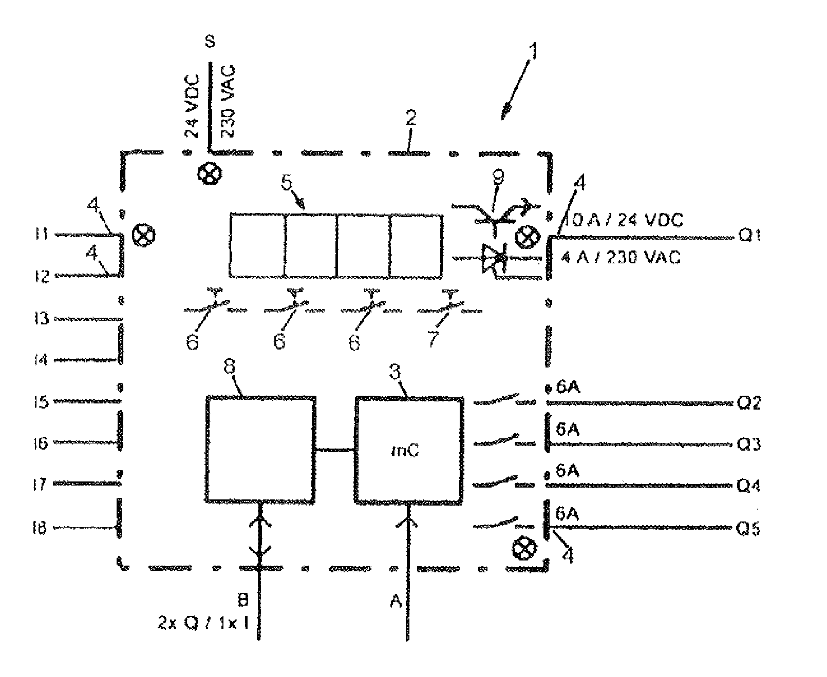
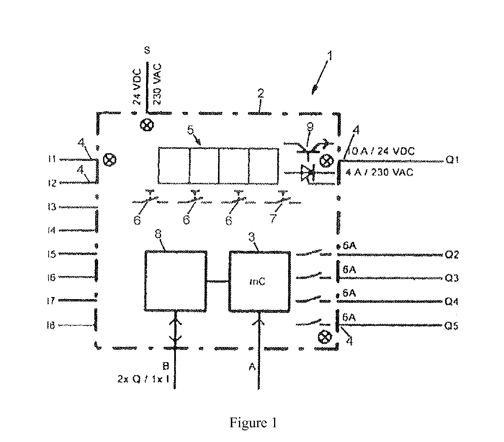
[0008]FIG. 1 shows a control device 1 with a housing 2 that is schematically indicated in the form of a dot-dash line and in which a control processor 3 is arranged. The housing 2 is provided with externally accessible terminals 4 for a sensor input I1 to I8 and a control output Q1 to Q5 that are respectively connected to the control processor 3. The sensor inputs I can be selectively read by the control processor 3 and the control outputs Q can be selectively switched by the control processor 3.

[0009]The control device 1 furthermore features an operator interface 5 that is fixed on the outside of the housing and connected to the control processor 3, wherein said operator interface contains, in particular, not-shown input and display units. The operator interface 5 serves for inputting control parameters of the control device 1 that is preset for a certain lubrication system.

[0010]For this purpose, the control processor 3 is set up with different control programs for different lubri...


PUM


Abstract

The invention relates to a control device for lubrication systems, having a control processor which is arranged in a housing, having connections, which are formed on the housing, for sensor inputs and control outputs, which are connected to the control processor, and having an operator interface which is secured to the outside of the housing and is intended to input control parameters. Provision is made for the control processor to be set up with different control programs for different lubrication systems and for program switches for selecting the different control programs to be arranged inside the housing.

Description

FIELD OF THE INVENTION[0001]The invention pertains to a control device for lubrication systems with a control processor that is arranged in a housing, wherein the housing features terminals for sensor inputs and control outputs that are connected to the control processor, and wherein an operator interface for inputting control parameters is fixed on the outside of the housing.BACKGROUND OF THE INVENTION[0002]Control devices of this type that are adapted to a special lubrication system are frequently utilized in practical applications for controlling and monitoring lubrication systems in technical facilities such that the desired lubricating effect is achieved. It is possible, for example, to determine the state of the facility or a lubricating requirement by means of sensors and to supply certain locations of the facility with lubricants by means of actuators that are connected to the control output and consist, for example, of pumps, valves or the like.SUMMARY OF THE INVENTION[0003...

Claims


Application Information

Patent Timeline
IPC IPC(8): G05B19/10G05D7/06H05K5/02
CPCG05B19/106G05B2219/23332G05B2219/2618G05B2219/25257G05B2219/23436G05B19/10
Inventor GUENTHER, ARMIN
Owner LINCOLN GMBH
Why Eureka
Try Eureka