
Blow molding machine for containers and mandrel holder
a molding machine and mandrel technology, applied in the direction of conveyors, rotary conveyors, transportation and packaging, etc., can solve the problems of troublesome handling, non-positive support of positive locking, and not suited to different mouth types, so as to achieve short stroke, reduce labor intensity, and reduce labor intensity
- Summary
- Abstract
- Description
- Claims
- Application Information
AI Technical Summary
Benefits of technology
Problems solved by technology
Method used
Image

Examples
Embodiment Construction
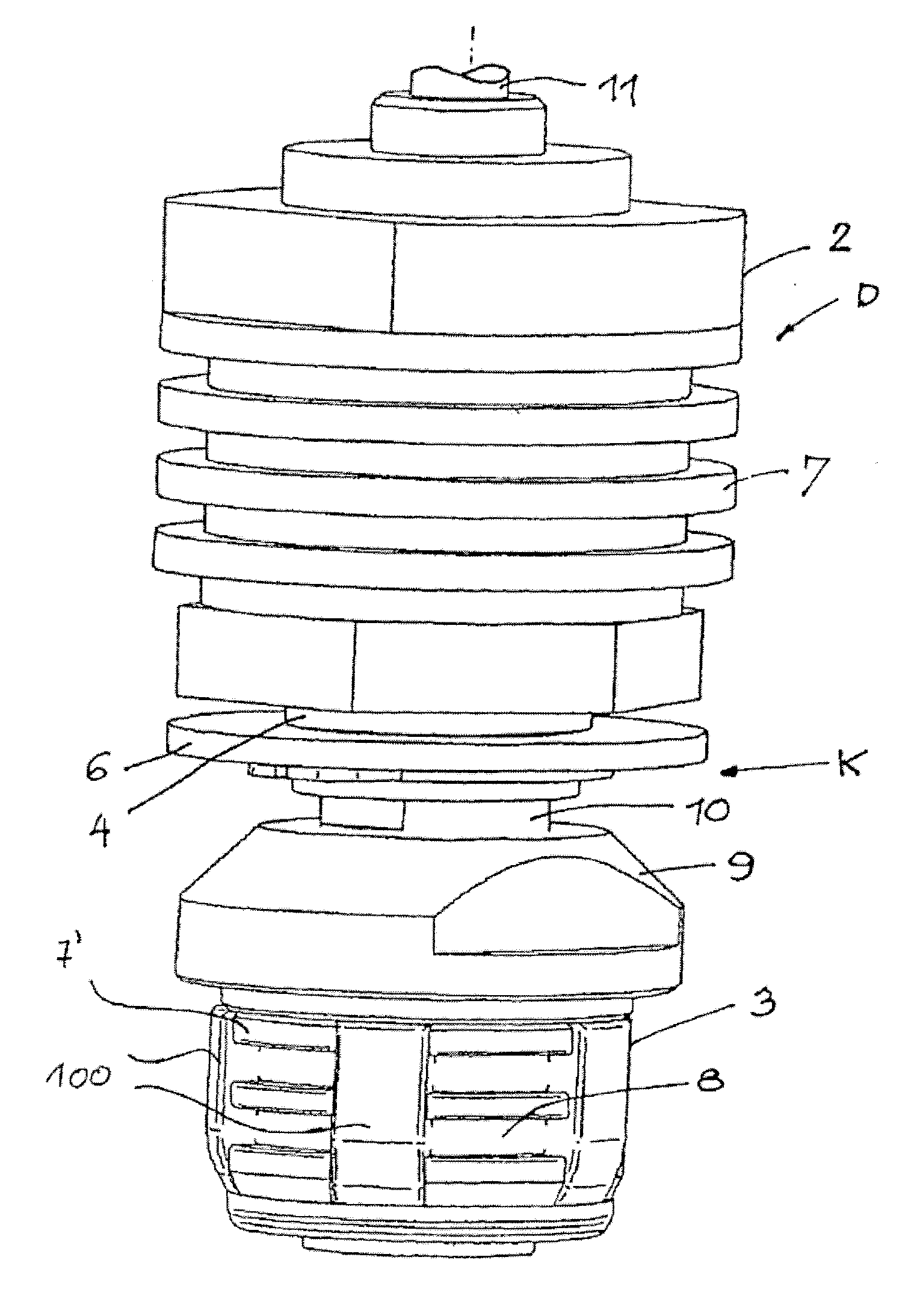
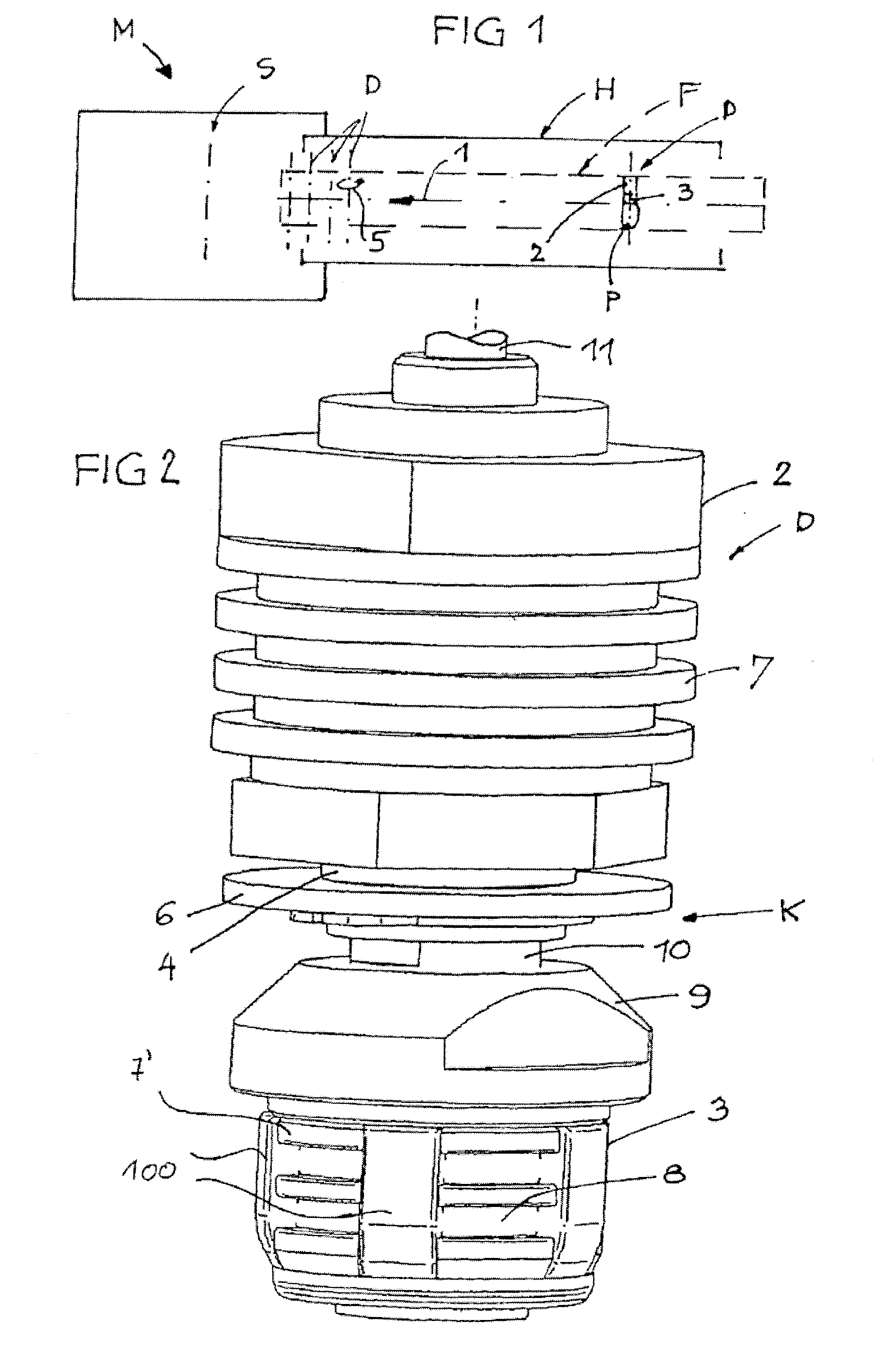
[0030]FIG. 1 schematically illustrates a blow molding machine M for containers, for example a stretch-blow molding machine for plastic bottles. A blowing station S with a non-depicted blow molding star is connected to a conveyor path F which at least in sections runs through a heating device H for preforms P to be heated or to be treated thermally. The conveyor path F in operation moves in the conveying direction 1 and contains a plurality of mandrel devices D placed close to each other, each consisting of a mandrel holder 2 transportable in the conveyor path F and mounted to be suspended in this case, and a pre-forming mandrel 3 attached thereto in an exchangeable manner, onto which one preform P each can be placed. The mandrel devices D are possibly rotated about their axes in the sense of rotation 5 in operation.
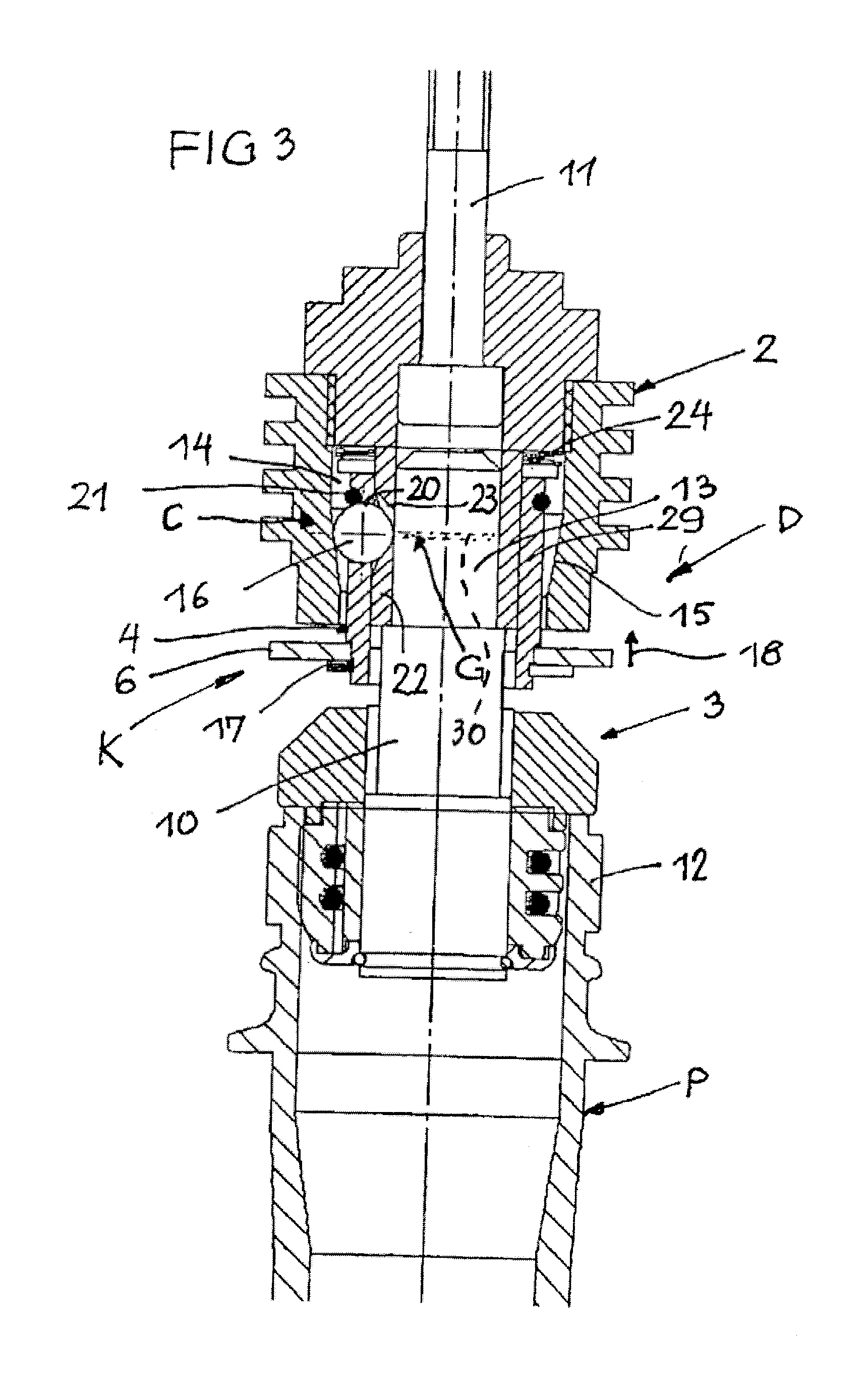
[0031]According to FIGS. 2 and 3, the pre-forming mandrel 3 is mounted at the mandrel holder 2 mounted via a shaft 11 in an exchangeable manner by means of a releasable c...
PUM
| Property | Measurement | Unit |
|---|---|---|
| thermal stress | aaaaa | aaaaa |
| time | aaaaa | aaaaa |
| retention force | aaaaa | aaaaa |
Abstract
Description
Claims
Application Information