Toroidal continuously variable transmission

a technology of continuous variable transmission and rotating shaft, which is applied in the direction of belt/chain/gearing, friction gearing, belt/chain/gearing, etc., can solve the problems of unavoidable cost increase, troublesome manufacturing, management and assembly work of parts, and difficult to maintain the durability of thrust ball bearings, so as to maintain the durability of toroidal continuously variable transmission and maintain the surface pressure. , the effect of maintaining the durability of the thrust rolling bearing

Active Publication Date: 2011-06-02
NSK LTD
View PDF1 Cites 12 Cited by
  • Summary
  • Abstract
  • Description
  • Claims
  • Application Information

AI Technical Summary

Benefits of technology

[0077]Moreover, both surfaces come in contact at two locations that are separated in the circumferential direction of these surfaces, so even when a large thrust load is applied to the outer race, the outer race can be kept from elastically deforming in the direction narrowing the width of the opening of this concave section. Therefore, the interval between the outer race track formed on the inside surface of the outer race and the inner race track formed on the outside surface of the power roller is kept from becoming uneven in the circumferential direction of these tracks. Consequently, it is possible to keep the surface pressure at the area of rolling contact between these tracks and the rolling bodies (balls) from becoming partially excessive. As a result, it is possible to maintain durability of the thrust rolling bearing, as well as maintain the durability of the toroidal continuously variable transmission in which the thrust rolling bearing is assembled.
[0078]Furthermore, by smoothly connecting the edges on the ends on the center side of both side concave curved surface sections and edges on both sides of the center concave curved surface section, it is possible to reduce stress that is applied at or near the bottom section of the concave section due to pressure between the inner surface of the concave section and the cylindrical convex surface of the support beam section, even when a large force is applied in a direction that would separate both side concave curved surface sections from each other. As a result, it is possible to prevent damage such as cracking from occurring to the outer race.
[0079]In addition, in the construction of the preferred embodiment of the present invention that increases the rigidity of the trunnion by eliminating the need for forming a circular hole in the trunnion b

Problems solved by technology

In the case of the first example of this kind of conventional construction, construction for causing each power roller 8 to displace in the axial direction is complex, making the manufacturing, management and assembly work of parts troublesome and an increase in cost is unavoidable.
(2) It is difficult to maintain durability of the thrust ball bearing 17.
When deformation of the trunnion 9 becomes large, there is also a possibility that this deformation will cause problems such as cause the position of the contact point between the disks 1a, 1b, 6 and the power roller 8 to shift from the design value and cause the surface pressure to increase at that contact point, or that will cause the transmission ratio to shift.
In addition, when controlling the transmission by using a precession cam, the position of the precession cam shifts due to deformation of the trunnion 9, and this also becomes a major cause of shifting of the transmission ratio.
However, in this case, it is necessary that a track surface for the roller bearing be formed around the outer peripheral surface of the outer race 18, so there is a possibility that the processing cost will increase.
In addition, by using construction wherein the tangential force is supported by the outer peripheral surface of the outer race 18, there is a problem in that the deformation of the track groove portion of the outer race 18 becomes large as the stress at the portion on the inside surface side of the outer peripheral portion of the outer race 18 increases.
Moreover, due to this rolling resistance, there is a possibility that the transmission efficiency of the overall transmission will decrease.
However, the space between the trunnion 9a and the

Method used


Image

  • Toroidal continuously variable transmission
  • Toroidal continuously variable transmission
  • Toroidal continuously variable transmission

Examples


embodiment 1

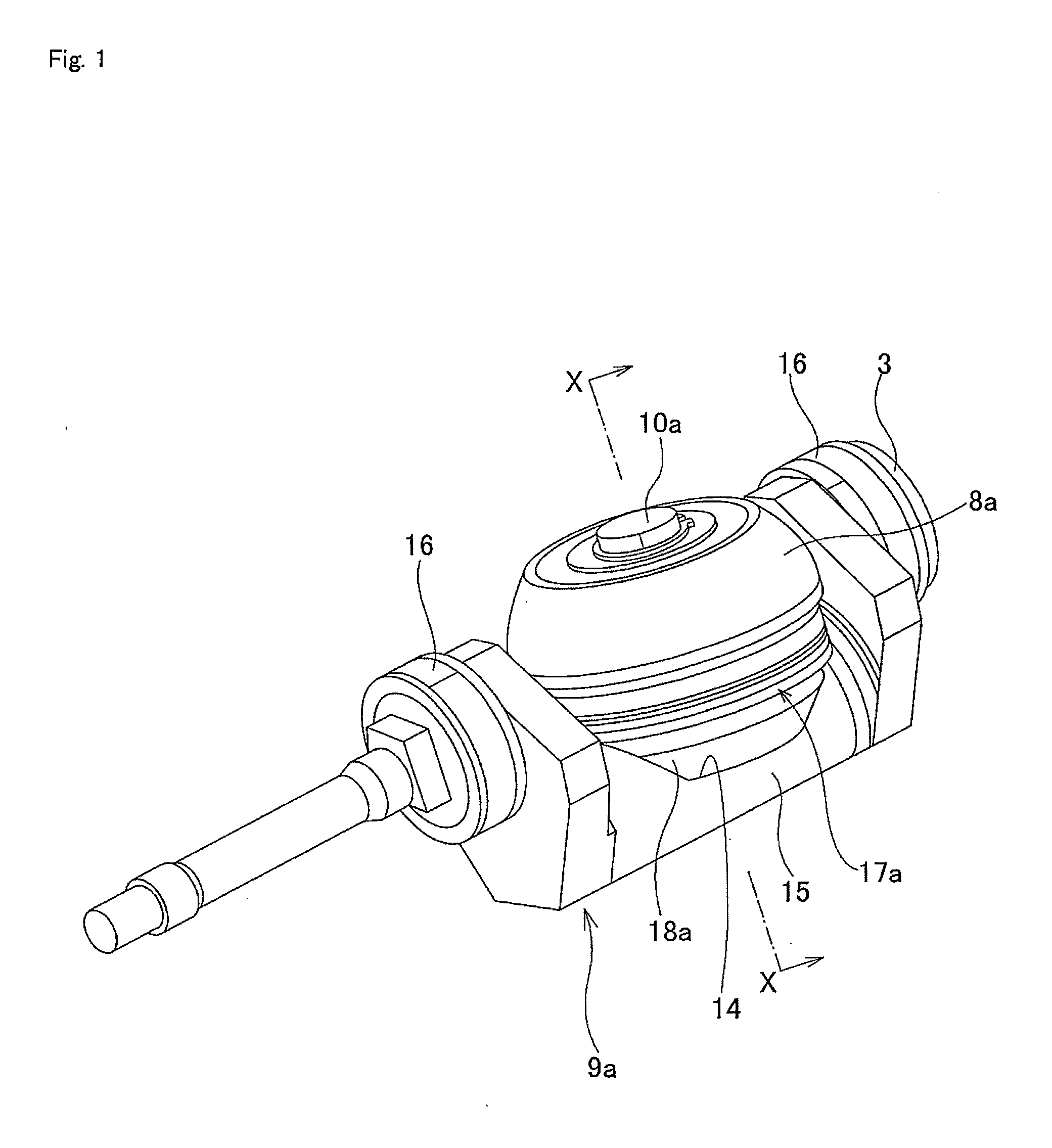
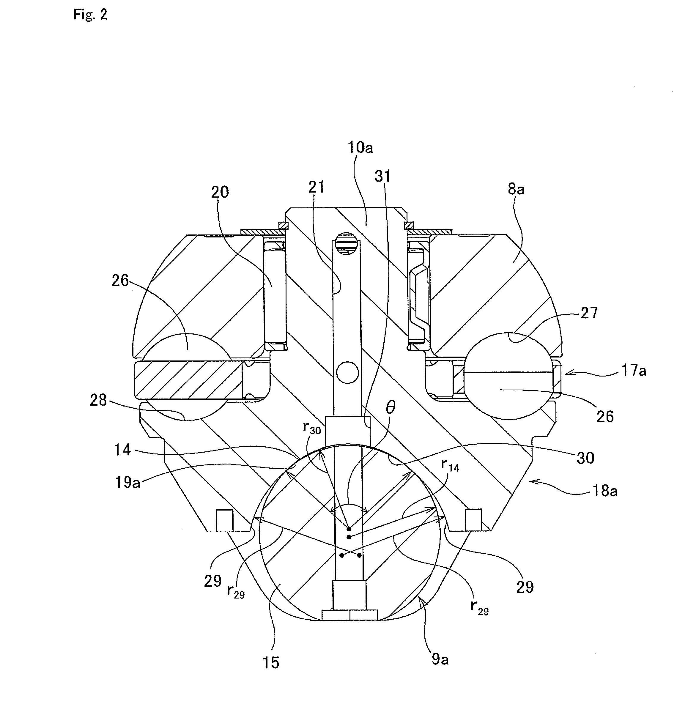
[0116]FIGS. 1 to 4 illustrate a first embodiment of the present invention. The feature of this embodiment is the maintaining of the durability of an outer race 18a and the thrust ball bearing 17a that comprises this outer race 18a by contriving a design for the shape of the inner surface of a concave section 19a that is formed on the outside surface of the outer race 18a in the radial direction of this outer race 18a. The construction and function of the other parts are the same as those of the second example of conventional construction illustrated in FIGS. 27 to 33 and described above, so the same reference numbers are given to identical parts, and any redundant explanation will be simplified or omitted, such that the explanation below can center on the features of this embodiment.

[0117]In the construction of this embodiment, the inner surface of the concave section 19a above is not a simple cylindrical surface, but rather has a Gothic arch shaped cross section that is formed by s...

embodiment 2

[0125]Next, a second embodiment of the present invention is explained. The feature of the toroidal continuously variable transmission of this embodiment is construction that transmits a tangential force that acts on the power roller by the outer peripheral surface of the outer race and the point of contact where the trunnion comes in contact with the outer peripheral surface of the outer race, while the other construction and function are the same as the construction and function of the first embodiment and conventional construction. Therefore, needless to say, the explanation will center on the featured parts of this embodiment, and for other parts, the same reference numbers as those used in FIGS. 1 to 6 and FIGS. 26 to 33 will be used to simplify the explanation.

[0126]As illustrated in FIG. 7 and FIG. 8, in the toroidal continuously variable transmission of this embodiment, as in the first embodiment, by using construction that transmits tangential force acting on the power rolle...

embodiment 3

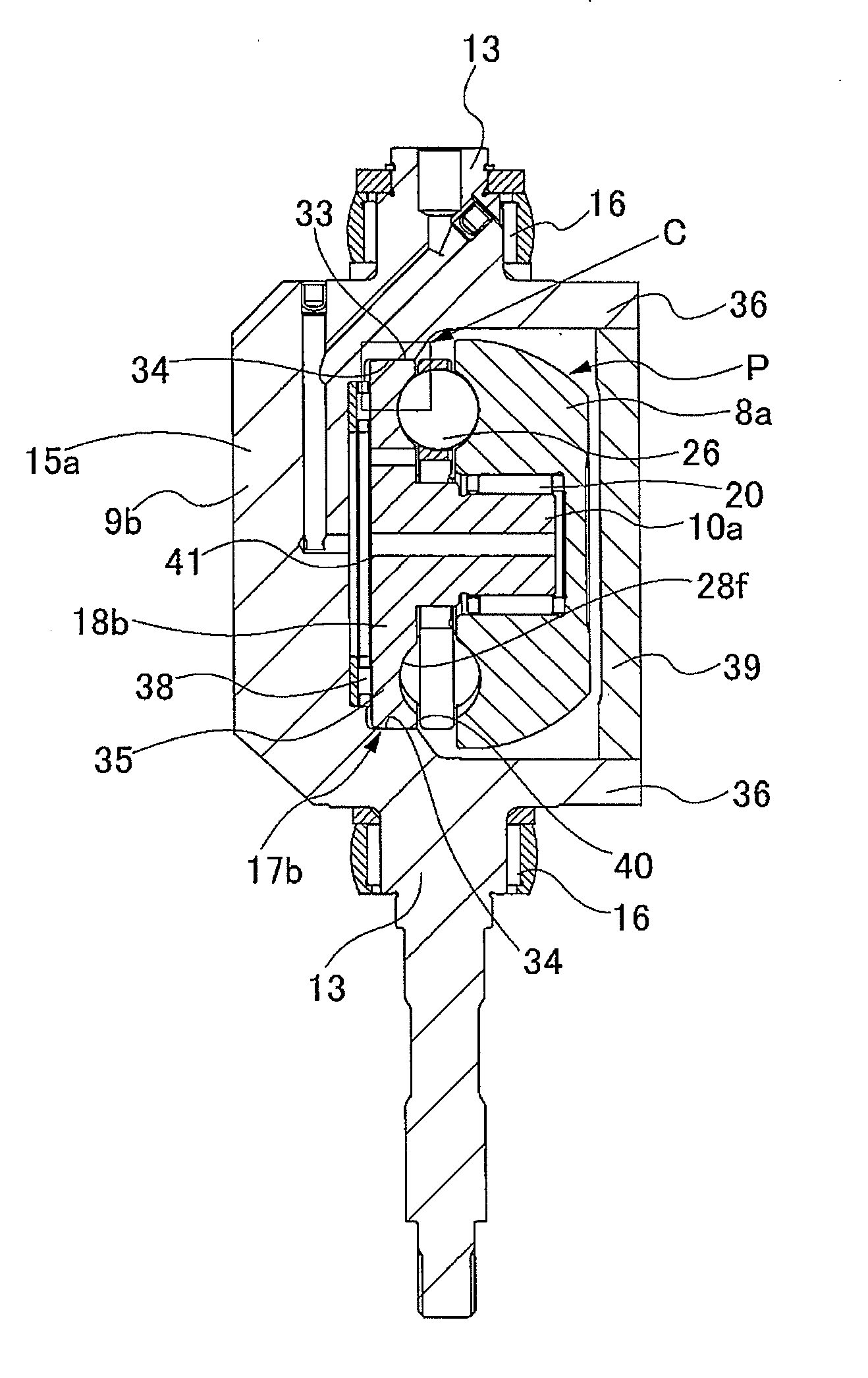
[0144]Next, a third embodiment of the present invention is explained. As illustrated in FIG. 9 and FIG. 10, in this embodiment, the width of the contact sections 34a of the trunnion 9c that comes in contact with the outer peripheral surface 33a of the main outer race section 35a along the direction of the axis of rotation of the power roller 8a, in other words, the width in the thickness direction from the inside surface 40 to the outside surface 41 of the main outer race section 35, is formed such that it becomes more narrow than that of the contact sections 34 of the second embodiment.

[0145]That is, in the second embodiment, the contact sections 34 are formed so that they cover the entire surface of the width in the thickness direction of the outer peripheral surface 33 of the main outer race section 35, however, in this third embodiment, construction is such that the contact sections 34 are formed only in the part from a little more on the inside surface 40 side than the center s...


PUM


Abstract

A toroidal continuously variable transmission of the present invention comprises: input side disks (1a, 1b) and output side disks (6) being supported concentric with each other such that the disks can rotate freely; a trunnion (9) that comprises end sections (36) on both ends on which tilt shafts (13) that are concentric with each other are provided, and a support beam section (15) that extends between both end sections (36), the trunnion (9) being capable of pivotally displacing around the tilt shafts (13); a thrust rolling bearing (17); and a power roller (8) that is supported to the inside surface of the trunnion (9) by way of the thrust rolling bearing (17) such that it rotates freely; wherein the support beam section (15) comprises an inside surface having a cylindrical convex surface (14); the thrust rolling bearing (17) comprises an outer race (18a) having an outside surface with a concave section (19a) that fits with the cylindrical convex surface (14) of the support beam section (15), and a plurality of rolling bodies (26) that are located between the power roller (8) and a track of an outer race (18a); and the concave section (19a) of the outer race (18a) has side surface sections (29) on both sides in the width direction, fits with the cylindrical convex surface (14) by the cylindrical convex surface (14) coming in contact with both side surface sections (29).

Description

BACKGROUND OF THE INVENTION[0001]1. Field of the Invention[0002]The present invention relates to a toroidal continuously variable transmission, and particularly to a half toroidal continuously variable transmission, that can be used as an automatic transmission for an automobile or as a transmission for all kinds of industrial machinery.[0003]2. Description of the Related Art[0004]The use of a toroidal continuously variable transmission as an automobile transmission, for example, is described in many publications, and the toroidal continuously variable transmission has been partially implemented and it has been well known. Particularly, toroidal continuously variable transmissions having various construction are disclosed in Japanese Patent Application Publication No. 2008-25821. FIG. 26 illustrates the basic construction of a currently implemented toroidal continuously variable transmission as disclosed in this document.[0005]First, a first example of this conventional construction...

Claims


Application Information

Patent Timeline
IPC IPC(8): F16H15/38
CPCF16H15/38
Inventor NISHII, HIROKISATO, TOSHIHIKOINOUE, EIJITOYODA, TOSHIROYOSHIOKA, HIROYASUSHIMOMURA, YUJIYAMAMOTO, SHIN
Owner NSK LTD
Why Eureka
Try Eureka