Plant for blow-moulding plastic containers, particularly bottles

Active Publication Date: 2011-06-23
SACMI COOP MECCANICI IMOLA S C R L
View PDF7 Cites 12 Cited by
  • Summary
  • Abstract
  • Description
  • Claims
  • Application Information

AI Technical Summary

Benefits of technology

[0009]This invention has for an aim to provide a blow-moulding plant for making plastic containers, particular

Problems solved by technology

Plants of the type described above have several disadvantages, due mainly to the fact that the presence of two transfer wheels or, alternatively, two ovens and two feed devices, makes these plants relatively complex and expensive.
This solution, too, however, is not free of disadvantages.
That is because the presen

Method used


Image

  • Plant for blow-moulding plastic containers, particularly bottles
  • Plant for blow-moulding plastic containers, particularly bottles
  • Plant for blow-moulding plastic containers, particularly bottles

Examples


Example

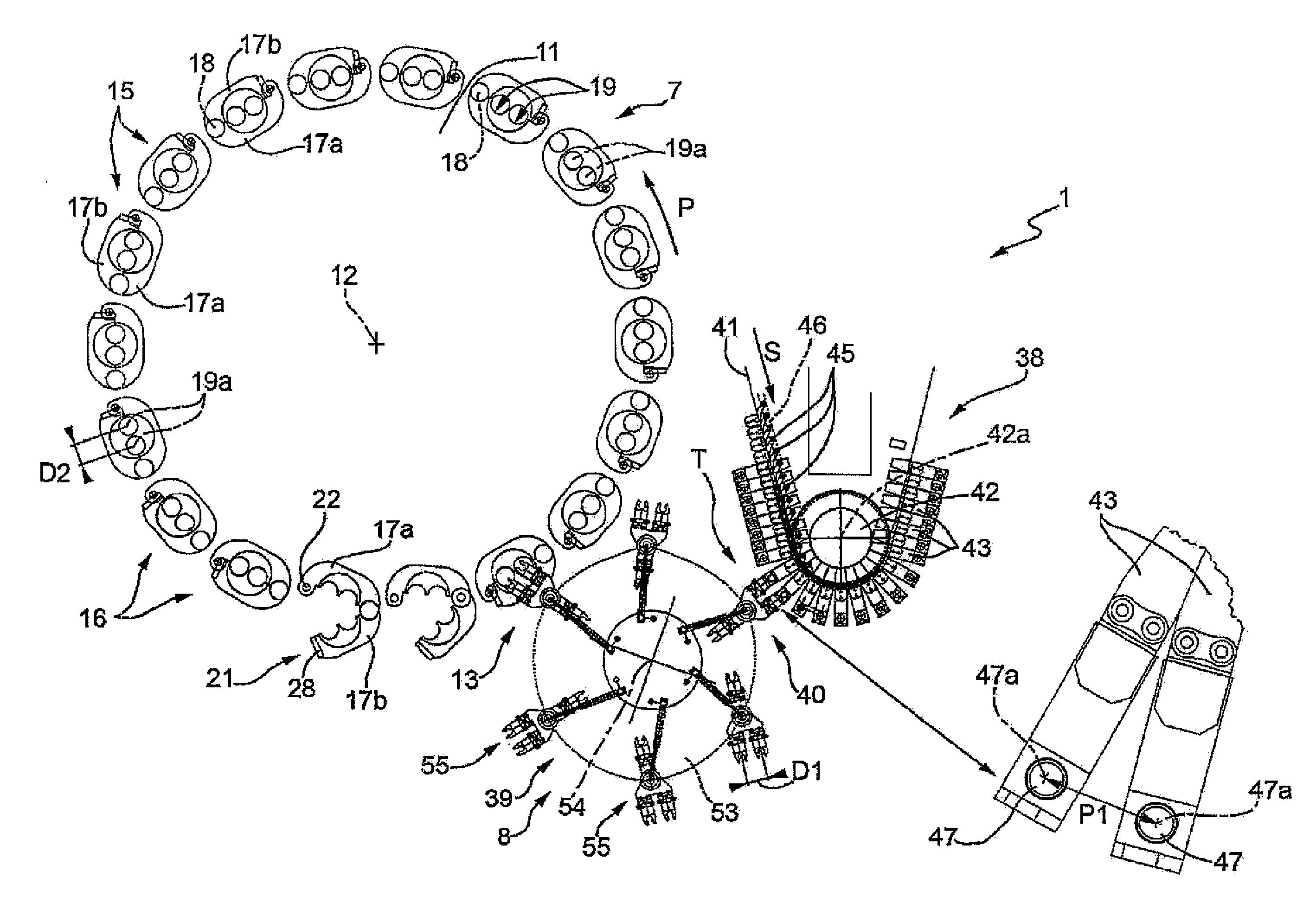
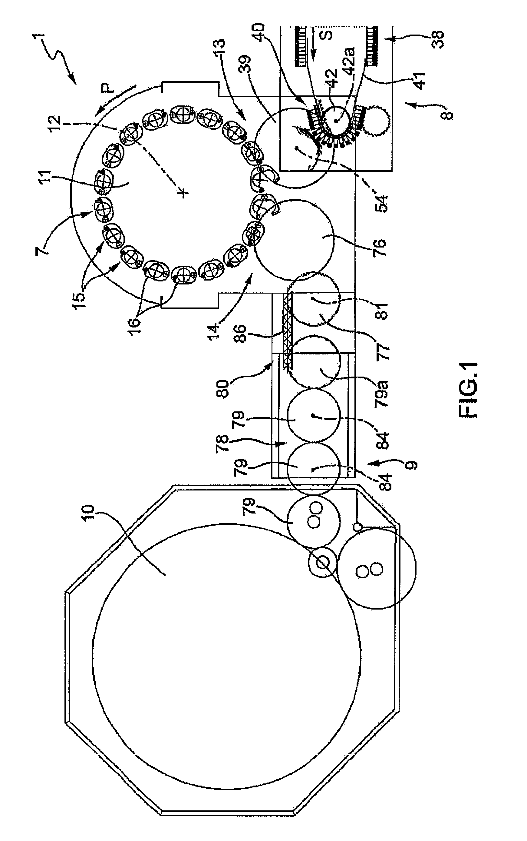
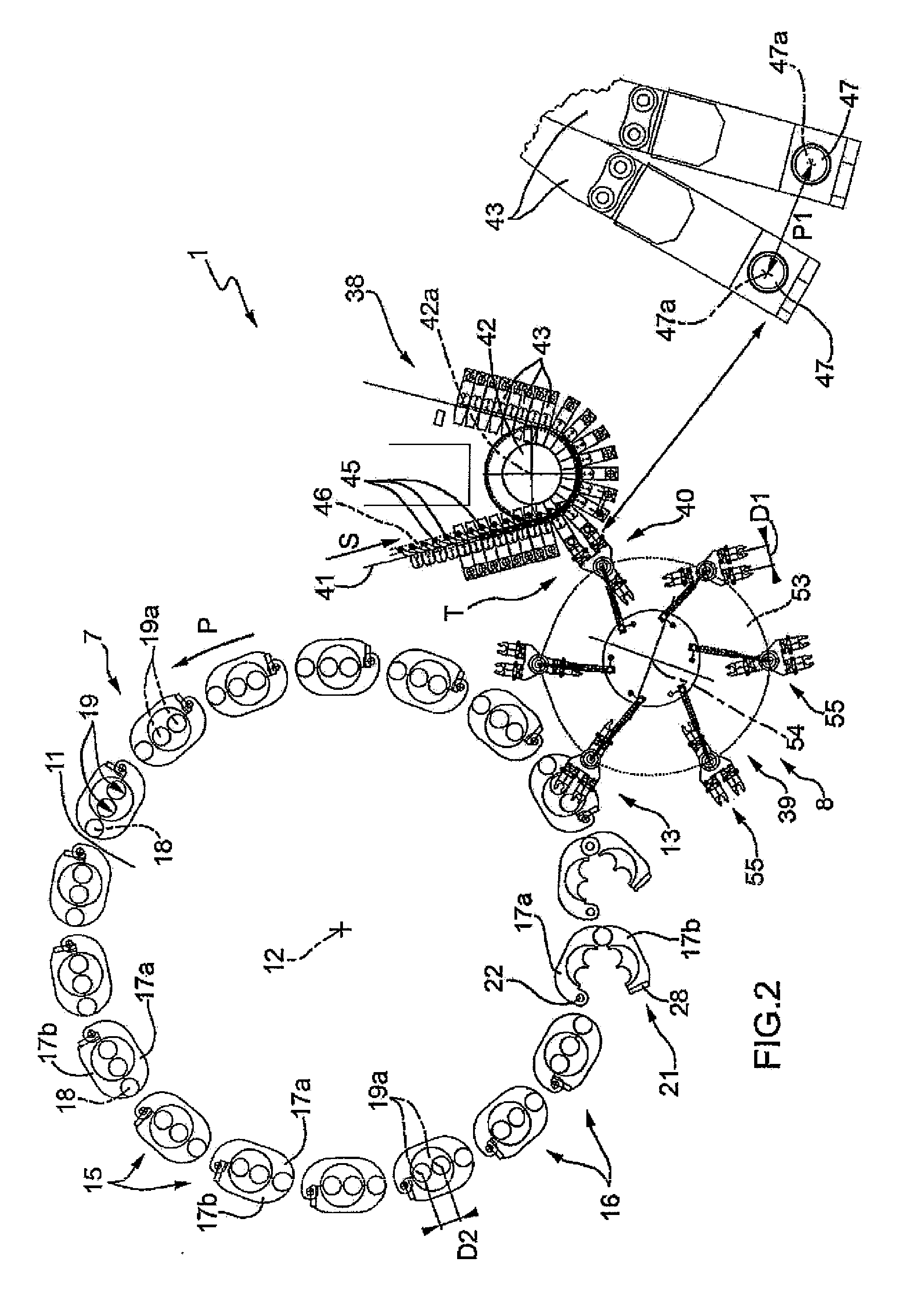
[0036]With reference to FIG. 1, the numeral 1 denotes in its entirety a plant for blow-moulding plastic containers, in this particular case, plastic bottles 2 (FIG. 9), from respective parisons 3 of known type (FIG. 5), each of which comprises an elongated cup-shaped body 4 having an externally threaded open end 5, and an annular neck 6 extending radially outwards from the outside surface of the body 4 itself.

[0037]The plant 1 comprises a blow-moulding machine 7 for blow-moulding the bottles 2, a line 8 for feeding the parisons 3 to the machine 7, and a line 9 for feeding the bottles 2 from the machine 7 to a customary filling machine 10.

[0038]As illustrated in FIGS. 1 and 2, the machine 7 comprises a blow-moulding wheel 11 mounted in such a way as to rotate continuously (counterclockwise in FIGS. 1 and 2) about its longitudinal axis 12, which is substantially vertical and at right angles to the drawing plane of FIGS. 1 and 2. The wheel is connected to the lines 8 and 9 at a first a...


PUM

PropertyMeasurementUnit
Flexibilityaaaaaaaaaa

Abstract

A plant for blow-moulding plastic containers (2), particularly bottles, from respective parisons (3) is equipped with a plurality of moulding units (15), each having at least two respective cavities (19) for blow-moulding respective containers (2), and with a transfer device (39) for transferring the parisons (3) from a flexible feed conveyor (41) to the respective moulding cavities (19). The transfer device (39) is connected to the flexible feed conveyor (41) at a transfer station (40), where the spacing (P1) of the parisons (3) is equal to the distance (D2) between the longitudinal axes (19a) of the moulding cavities (19) of one moulding unit (15).

Description

TECHNICAL FIELD[0001]This invention relates to a plant for blow-moulding plastic containers, particularly bottles.BACKGROUND ART[0002]In the bottling industry, prior art plant for making plastic bottles comprises: a blow-moulding wheel mounted in such a way as to rotate about its longitudinal axis and equipped with a plurality of blow-moulding units, each of which is rotationally fed by the blow-moulding wheel about this axis and comprises two cavities for blow-moulding respective bottles; an oven for thermally conditioning the parisons; a feed device for advancing the parisons through the oven according to a first, predetermined spacing; and a transfer device for transferring the parisons from the feed device to the blow-moulding cavities.[0003]Since the first predetermined spacing is normally smaller than the distance between the longitudinal axes of the moulding cavities of one blow-moulding unit, the transfer device comprises a first variable spacing transfer wheel designed to p...

Claims


Application Information

Patent Timeline
IPC IPC(8): B29C49/64B29C49/36B29C49/42
CPCB29C49/06B29C49/36B29C49/4205B29C2049/4221B29C49/4236B29C49/64B65G47/847B29C49/4215B29C49/42105B29C49/42122B29C49/42071B29C49/42095B29C49/42155B29C2949/0715B29C49/42B65G47/84B65G29/00
Inventor BORGATTI, MAURIZIOMOROVINGI, MASSIMOPARRINELLO, FIORENZORE, EMILIOSTOCCHI, GABRIELE
Owner SACMI COOP MECCANICI IMOLA S C R L
Why Eureka
Try Eureka