Method of fabricating a metallic microstructure and microstructure obtained via the method

a technology of which is applied in the field of method of fabricating metallic microstructure and microstructure obtained via the method, can solve the problems of inability to meet the requirements of microstructure mass production, and inability to meet the requirements of low unit cos

Active Publication Date: 2011-01-27
NIVAROX FAR
View PDF3 Cites 6 Cited by
  • Summary
  • Abstract
  • Description
  • Claims
  • Application Information

AI Technical Summary

Benefits of technology

[0016]It is an object of the invention to overcome the aforementioned drawbacks in addition to others by providing a method for fabricating microstructures that are optimally adapted, from the point of view of their composition, to the application for which they are intended. The microstructures thereby obtained have geometrical dimensions whose precision is controlled.

Problems solved by technology

The quality of the microstructures obtained is not open to criticism, but the requirement to implement expensive equipment (the synchrotron) makes this technique incompatible with the mass production of microstructures that have to have a low unitary cost.
The microstructures obtained in accordance with the methods of the prior art are metallic microstructures made of a single metal, generally nickel, and copper, nickel-phosphorus, which is not always optimal depending upon the application for which they are intended.
Indeed, applications exist for which one or other of these materials does not have optimal properties, both from the mechanical and tribological point of view.
This type of method has, however, the drawback of not allowing parts to be obtained simply with controlled geometrical precision.

Method used


Image

  • Method of fabricating a metallic microstructure and microstructure obtained via the method
  • Method of fabricating a metallic microstructure and microstructure obtained via the method

Examples


Embodiment Construction

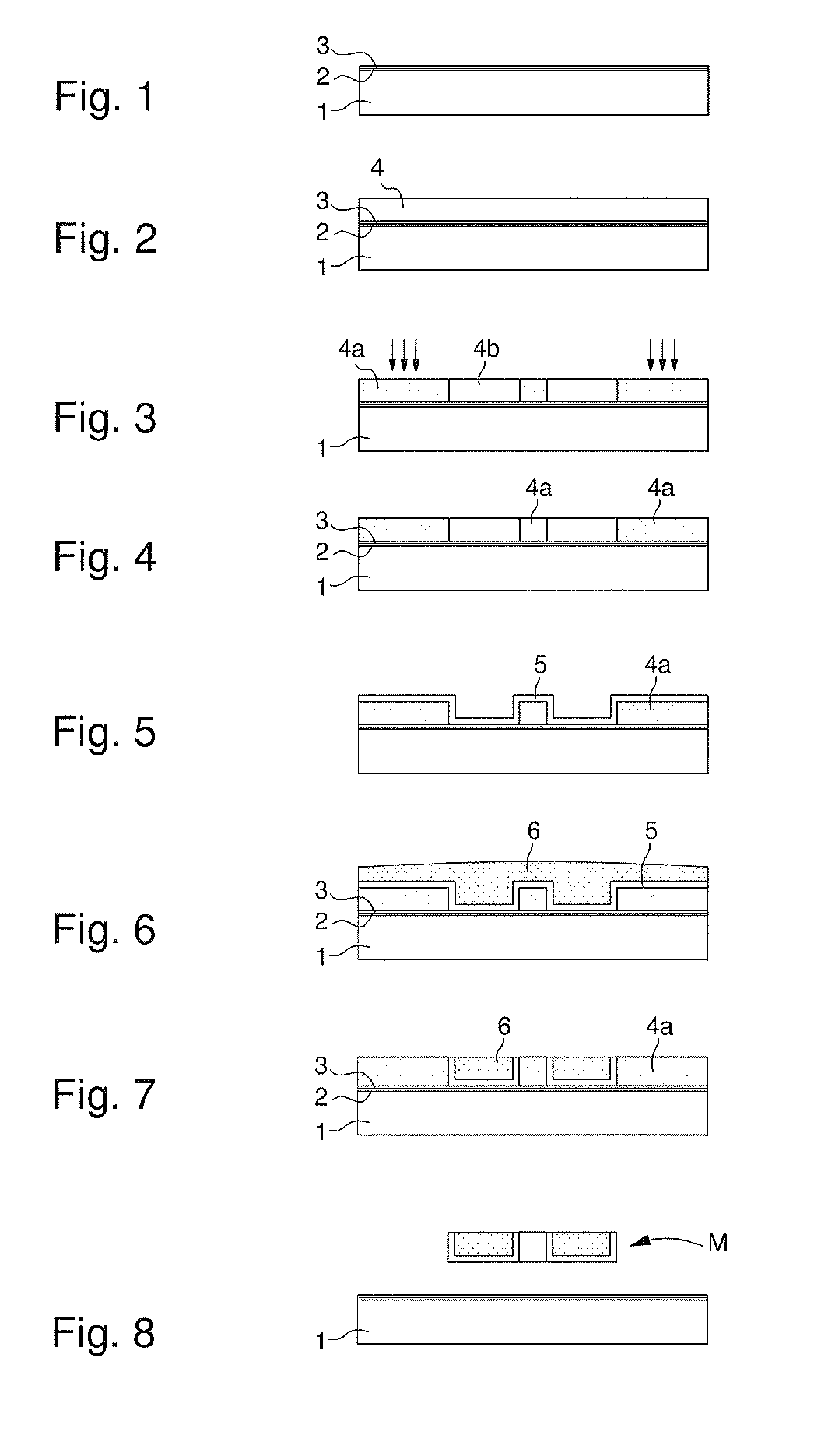
[0037]Substrate 1 used in step a) of the method according to the invention is, for example, formed by a silicon, glass or ceramic wafer on which a conductive priming layer is evaporation deposited, i.e. a layer able to trigger an electroforming reaction. The conductive, priming layer is typically formed of a chromium sub-layer 2 and a gold layer 3 (FIG. 1).

[0038]Alternatively, the substrate 1 could be formed of stainless steel or another metal able to trigger the electroforming reaction. In the case of a stainless steel substrate, the substrate will be cleaned first.

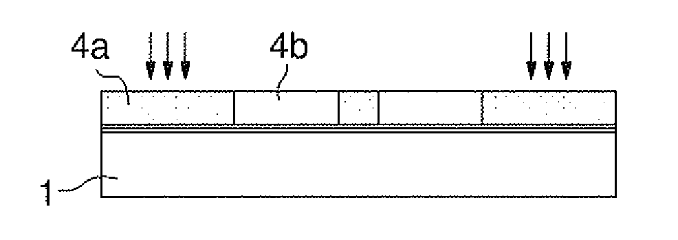
[0039]The photosensitive resin 4 used in step b) of the method according to the invention is preferably an octofunctional epoxy resin available from Shell Chemical under the reference SU-8 and a photoinitiator selected from among triarylsulfonium salts, such as those described in U.S. Pat. No. 4,058,401. This resin can be photopolymerised under the action of UV radiation. It will be noted that a solvent that has proved s...


PUM

PropertyMeasurementUnit
thicknessaaaaaaaaaa
thicknessaaaaaaaaaa
thicknessaaaaaaaaaa

Abstract

The invention concerns a method of fabricating a metallic microstructure, characterized in that it includes the steps consisting in forming a photosensitive resin mould by a LIGA-UV type process, and in the uniform, galvanic deposition of a layer of a first metal and then a layer of a second metal form a block, which approximately reaches the top surface of the photosensitive resin.

Description

[0001]This is a National Phase Application in the U.S. of International Patent Application PCT / EP2008 / 067969 filed Dec. 19, 2008, which claims priority on Swiss Patent Application No. 02036 / 07, filed Dec. 31, 2007. The entire disclosures of the above patent applications are hereby incorporated by reference.FIELD OF THE INVENTION[0002]The present invention concerns a method of fabricating a metallic microstructure via a LIGA type technology. In particular, the invention concerns a method of this type for fabricating a microstructure, which has a core made of a first metal, at least partially coated with a functional layer, of a second metal and wherein the precision of the geometrical dimensions are directly defined by the method. The invention also concerns a metal part of this type obtained via this method.BACKGROUND OF THE INVENTION[0003]LIGA technology (Lithographie Galvanik Abformung), developed by W. Ehrfeld of the Karlsruhe Nuclear Research Centre, Germany in the 1980s, has pr...

Claims


Application Information

Patent Timeline
Patent Type & Authority Applications(United States)
IPC IPC(8): G03F7/20
CPCC25D5/022C25D5/024C25D5/12C25D1/006C25D7/005C25D7/10C25D7/00
Inventor FIACCABRINO, JEAN-CHARLES
Owner NIVAROX FAR
Why Eureka
Try Eureka