Inverter-filter non-linearity blanking time and zero current clamping compensation system and method

a compensation system and zero current technology, applied in the direction of electric variable regulation, process and machine control, instruments, etc., can solve the problems of reducing the rms deteriorating the total harmonic distortion (thd) affecting the operation so as to reduce the total harmonic distortion of the output voltage, simple and inexpensive implementation, and easy implementation in dsp software

Active Publication Date: 2008-07-08
GE HYBRID TECH
View PDF5 Cites 7 Cited by
  • Summary
  • Abstract
  • Description
  • Claims
  • Application Information

AI Technical Summary

Benefits of technology

[0012]It is a further object of this invention to provide such an improved, non-linear compensation system and method which reduces total harmonic distortion in the output voltage.
[0013]It is a further object of this invention to provide such an improved, non-linear compensation system and method which is simple and inexpensive to implement.
[0014]It is a further object of this invention to provide such an improved, non-linear compensation system and method which is easily implemented in DSP software without added circuitry or components.

Problems solved by technology

In an open-loop system or a closed loop system controlling the RMS value, the output voltage experiences a distortion due to the filter inductance and the natural operation of the semiconductor devices.
This particular distortion reduces the RMS of the output voltage and deteriorates the total harmonic distortion (THD) of the output voltage, often in excess of conventional standards.
A compensation for the voltage error due to the blanking time is difficult to implement in the case of an inverter-filter system due to the multiple crossings of the zero axis of the current.
This simple compensation is close to the requirements for a RMS value of the output voltage within + / −5% of nominal but does not correct the THD of the output voltage.
A slight angular error may produce a glitch in the voltage waveform.
Unfortunately, the inverter-filter case is more complex and the blanking time cannot be compensated alone without considering the zero current clamping.
Zero current clamping is an issue each time the current crosses zero, where the conduction changes from an IGBT device to the anti-parallel diode.
There is not enough energy in the load circuit to turn on the anti-parallel diode and there is no voltage before the IGBT is actually turned-on by the control.
At high switching frequencies, this affects the quality of the output voltage waveform.

Method used


Image

  • Inverter-filter non-linearity blanking time and zero current clamping compensation system and method
  • Inverter-filter non-linearity blanking time and zero current clamping compensation system and method
  • Inverter-filter non-linearity blanking time and zero current clamping compensation system and method

Examples


Embodiment Construction

[0037]Aside from the preferred embodiment or embodiments disclosed below, this invention is capable of other embodiments and of being practiced or being carried out in various ways. Thus, it is to be understood that the invention is not limited in its application to the details of construction and the arrangements of components set forth in the following description or illustrated in the drawings. If only one embodiment is described herein, the claims hereof are not to be limited to that embodiment. Moreover, the claims hereof are not to be read restrictively unless there is clear and convincing evidence manifesting a certain exclusion, restriction, or disclaimer.

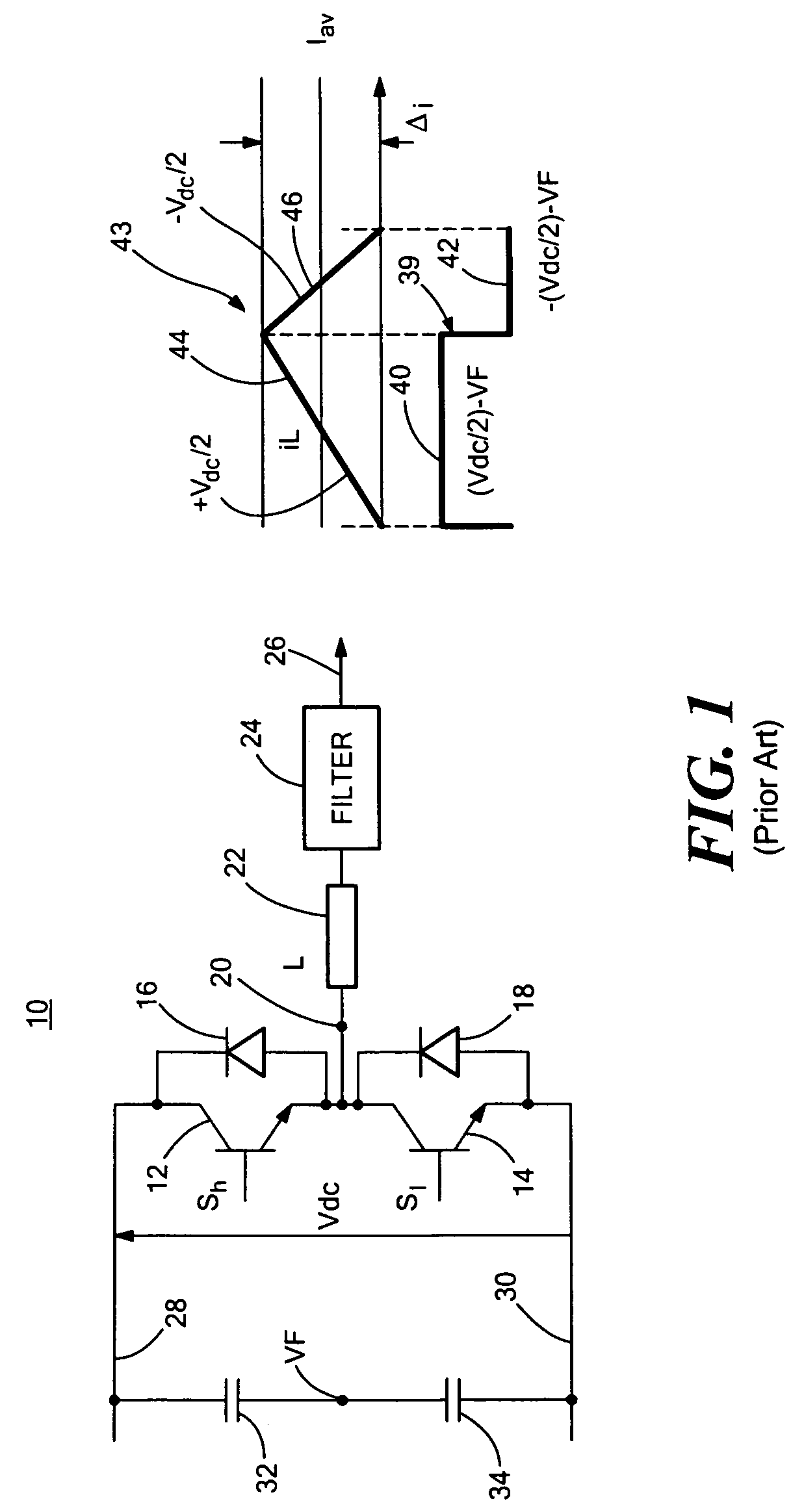
[0038]There is shown in FIG. 1, one inverter leg 10 of a conventional, prior art, three phase inverter-filter. Inverter-filter 10 includes a pair of switches 12, 14, such as insulated gate bi-polar transistors (IGBTs), each paralleled by a diode 16, 18 respectively. Switching signals Sh and Sl are applied to the bases of sw...


PUM


Abstract

Inverter-filter non-linearity blanking time and zero current clamping compensation is accomplished by comparing the average output current with the discontinuous current mode threshold values to determine when the average output current is entering a discontinuous current mode and introducing a compensation voltage to the inverter drive voltage in response to the average output current entering a discontinuous current mode to compensate for discontinuous current mode distortion of the inverter output voltage.

Description

FIELD OF THE INVENTION[0001]This invention relates to an inverter-filter non-linearity blanking time and zero current clamping compensation system and method.BACKGROUND OF THE INVENTION[0002]Sinusoidal voltages can be generated in a single-phase or three-phase configuration through a power converter followed by a passive filter. In an open-loop system or a closed loop system controlling the RMS value, the output voltage experiences a distortion due to the filter inductance and the natural operation of the semiconductor devices. This particular distortion reduces the RMS of the output voltage and deteriorates the total harmonic distortion (THD) of the output voltage, often in excess of conventional standards.[0003]An auxiliary power distribution system (APDS) is comprised of an inverter and a passive filter. Different filter topologies have been used to cancel the effects of the harmonics produced by the switching operation of the pulse width modulation (PWM) inverter. These filter t...

Claims


Application Information

Patent Timeline
Patent Type & Authority Patents(United States)
IPC IPC(8): H02M1/12H02H7/122
CPCH02M1/088H02M7/538466H02M7/53832H02M2001/385H02M1/385
Inventor NEACSU, DORIN O.
Owner GE HYBRID TECH
Why Eureka
Try Eureka