Cascaded flying capacitor modular high voltage inverters

a high-voltage inverter and cascade technology, applied in the field of power inverters, can solve the problems of high switching loss, adversely affecting the harmonic content of output waveforms, and conventional medium-voltage power inverter designs that produce compromised outputs, etc., to achieve the effect of reducing the number of cascaded stages, reducing the total harmonic distortion, and increasing the flexibility of system design

Active Publication Date: 2012-03-27
DRS NAVAL POWER SYST INC
View PDF12 Cites 41 Cited by
  • Summary
  • Abstract
  • Description
  • Claims
  • Application Information

AI Technical Summary

Benefits of technology

[0007]Methods and systems consistent with the present invention provide a medium voltage inverter having a variable voltage, variable frequency, and medium voltage output. The inverter may be, for example, a drive or power supply. The inverter beneficially includes a reduced number of cascaded stages required to synthesize a given output voltage level, without increasing the total harmonic distortion in the output waveforms. The inverter includes a plurality of multiple level flying capacitor inverter modules connected in series at their alternating current (AC) terminals to produce a desired AC output. Each k-level flying capacitor module can generate waveforms with the same harmonic fidelity as k−1 series two level H-bridges. The flying capacitor converter enables expansion above three levels at the cell level unlike conventional diode clamped converters. The availability of multiple voltages at the cell level, in combination with the cascaded structure provides increased flexibility in designing the system, while reducing the total number of cells. Each cell can accept a higher input DC voltage compared to conventional two-level inverters, yet may use the same switches as conventional two-level inverters. If this input voltage is generated from a transformer winding through a rectifier, the number of stages may be correspondingly reduced.

Problems solved by technology

Conventional medium voltage power inverter designs typically produce compromised results.
For example, medium voltage drives and power supplies have been synthesized using high voltage devices, but these typically have high switching losses which adversely affects the output waveform harmonic content.
The conventional medium voltage drive usually operates at medium voltages of 4.16 kV to 13.2 kV as operation at voltages substantially lower than 4.16 kV leads to excessive currents and power losses.
While a conventional medium voltage drive can be manufactured using a standard high voltage power semiconductor, the selection and availability of standard high voltage power semiconductors are limited.
In addition, conventional high voltage power semiconductors typically are severely lacking in switching speed, thus limiting the switching frequency.
In addition, conventional medium voltage drives typically require specialized multi-level circuitry that tends to increase the dollar cost per kva of the drive.
However, these conventional low voltage drives are not by themselves suited for controlling 5 MW to 75 MW loads or processes.
Low voltage devices have been used in a series configuration, however, voltage sharing and balance during switching events is typically difficult and waveform harmonic content remain high.
Conventional diode clamped and flying capacitor three-level converters allow a doubling of the dc bus and output voltage for a given switching device, but this voltage level is still limited by the device ratings.
While the output harmonics are still excessive.
However, the number of cells required to synthesize medium voltages is excessive, and this directly correlates to an increase in the number of secondary transformer windings required to generate the dc source.

Method used


Image

  • Cascaded flying capacitor modular high voltage inverters
  • Cascaded flying capacitor modular high voltage inverters
  • Cascaded flying capacitor modular high voltage inverters

Examples


Embodiment Construction

[0023]Reference will now be made in detail to an implementation in accordance with methods, systems, and articles of manufacture consistent with the present invention as illustrated in the accompanying drawings. The same reference numbers may be used throughout the drawings and the following description to refer to the same or like parts.

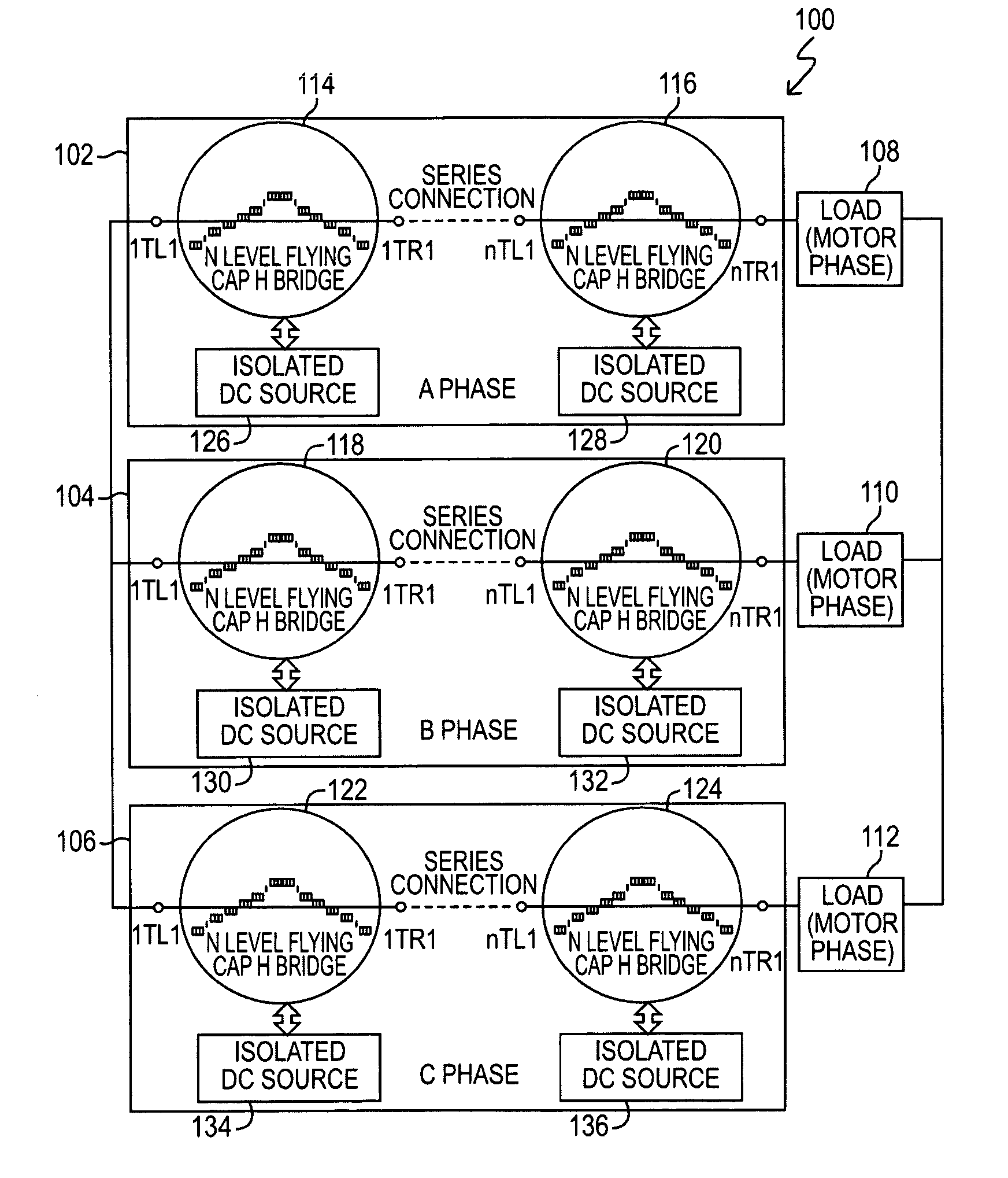
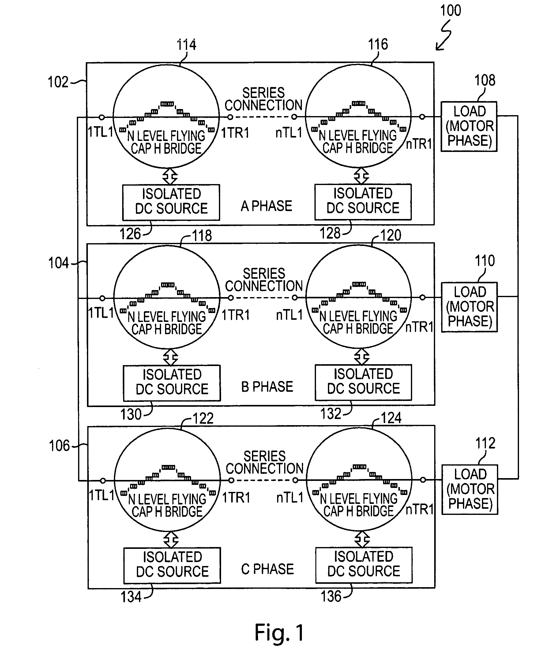
[0024]FIG. 1 shows an illustrative cascaded flying capacitor multi-level inverter 100 consistent with the present invention. The illustrative inverter is a three-phase wye connected inverter, where each phase 102, 104, 106 consists of a plurality of multiple voltage level flying capacitor H bridge inverter modules (“FCHBIM” or “module”) connected in series. In the illustrative example, phase A 102 includes modules 114 and 116, phase B includes modules 118 and 120, and phase C includes modules 122 and 124.

[0025]A load 108, 110, 112 is connected at to each respective phase 102, 104, 106. The illustrative loads 108, 110, 112 are each shown as wye conne...


PUM


Abstract

A high voltage inverter is provided which includes a plurality of k-level flying capacitor H bridge modules, k being greater than 2, each having a positive dc terminal, a negative dc terminal, and two ac terminals, a connecting unit for connecting said ac terminals of said plurality of k-level flying capacitor H bridge modules in series to form a cascading set of modules, and a dc source connected to an ac source and having a transformer, a rectifier rectifying an output voltage of said transformer, and a capacitor connected between the positive and negative dc terminals.

Description

FIELD OF THE INVENTION[0001]The present invention generally relates to power inverters and more particularly to a cascaded flying capacitor modular high voltage inverter.BACKGROUND OF THE INVENTION[0002]Conventional medium voltage power inverter designs typically produce compromised results. For example, medium voltage drives and power supplies have been synthesized using high voltage devices, but these typically have high switching losses which adversely affects the output waveform harmonic content.[0003]A conventional variable frequency medium voltage drive typically is employed to drive a medium voltage motor for the control of 5 MW to 75 MW loads or processes. The conventional medium voltage drive usually operates at medium voltages of 4.16 kV to 13.2 kV as operation at voltages substantially lower than 4.16 kV leads to excessive currents and power losses. While a conventional medium voltage drive can be manufactured using a standard high voltage power semiconductor, the selecti...

Claims


Application Information

Patent Timeline
Patent Type & Authority Patents(United States)
IPC IPC(8): H02M7/48
CPCH02M7/483H02M7/49H02M7/4837
Inventor BENDRE, ASHISH R.KRSTIC, SLOBODAN
Owner DRS NAVAL POWER SYST INC
Why Eureka
Try Eureka