Phase cut dimming LED driver

a technology of led driver and phase cut, which is applied in the field of phase cut dimming led driver, can solve the problems of conventional phase cut dimming that needs to be solved, consume electrical power, waste power, etc., and achieve the effects of improving pf and thd, increasing dimming and control performance, and improving p

Active Publication Date: 2016-05-03
WARBIRD CAPITAL LLC
View PDF12 Cites 38 Cited by
  • Summary
  • Abstract
  • Description
  • Claims
  • Application Information

AI Technical Summary

Benefits of technology

[0006]One object of the present invention is to provide a novel phase cut dimming LED driver. The phase cut dimming LED driver in the present invention has better PF and THD than those of a conventional phase cut dimming LED driver so as to increase the dimming and control performance by operating in an “uninterrupted control mode” which allows for increased PF and lower THD.

Problems solved by technology

It consumes electrical power, and can be switched off in situations where enough illumination is present to save power.
In some cases the illumination device could be turned off to save power, however, in other cases the illumination device must be kept on, hence wasting power since the full intensity is generated.
However, with LED lighting, there are problems with the conventional phase cut dimming that needs to be solved.
On the other hand, while the total harmonic distortion (THD) of the conventional phase cut dimming can be lower than 30%, it is still too large for effective LED dimming.

Method used


Image

  • Phase cut dimming LED driver
  • Phase cut dimming LED driver
  • Phase cut dimming LED driver

Examples


Embodiment Construction

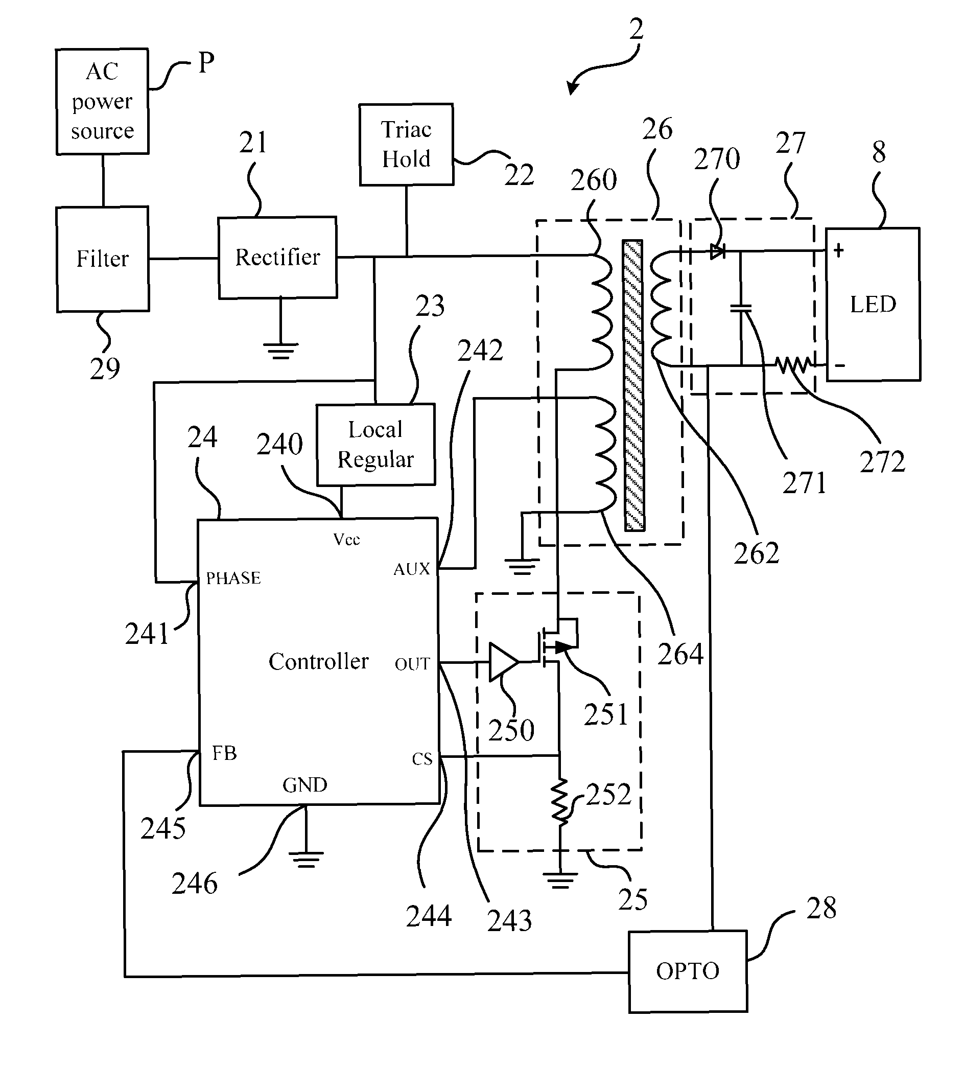
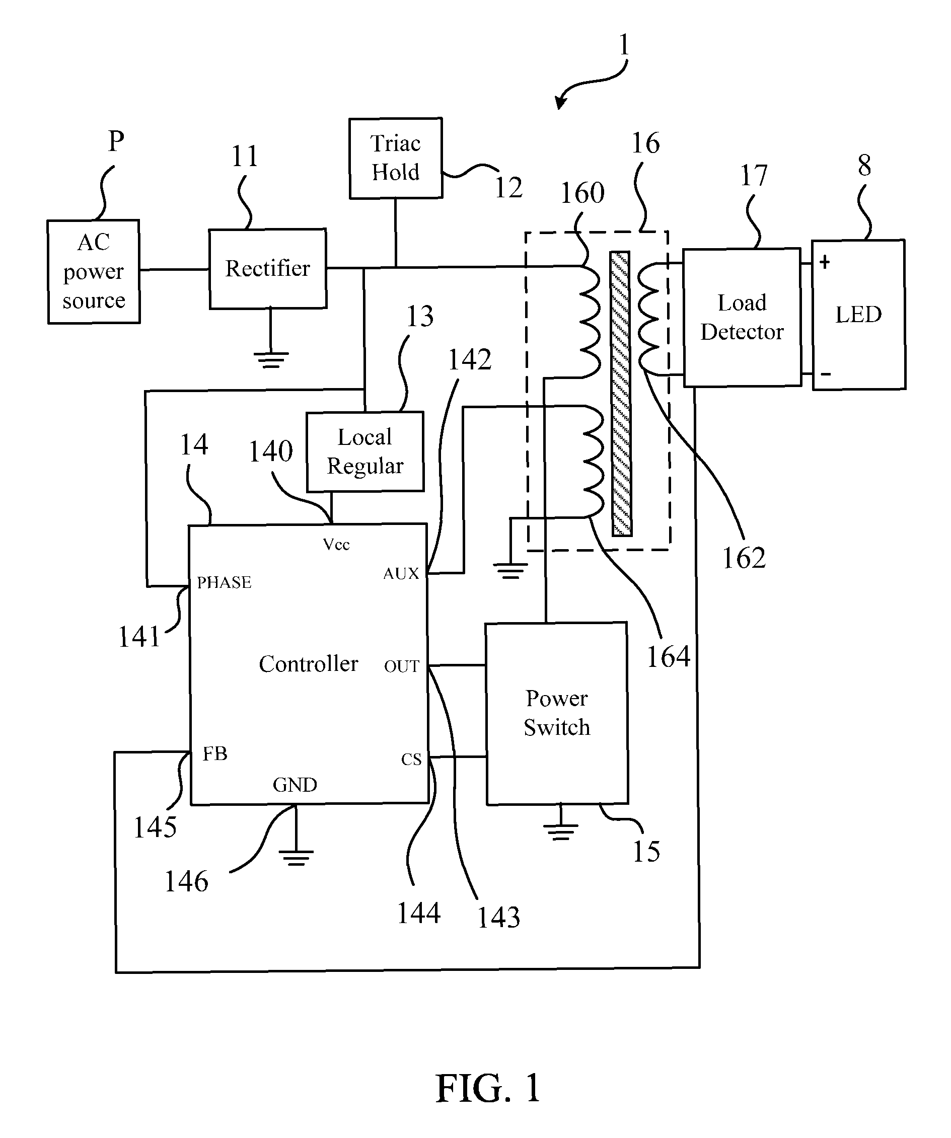
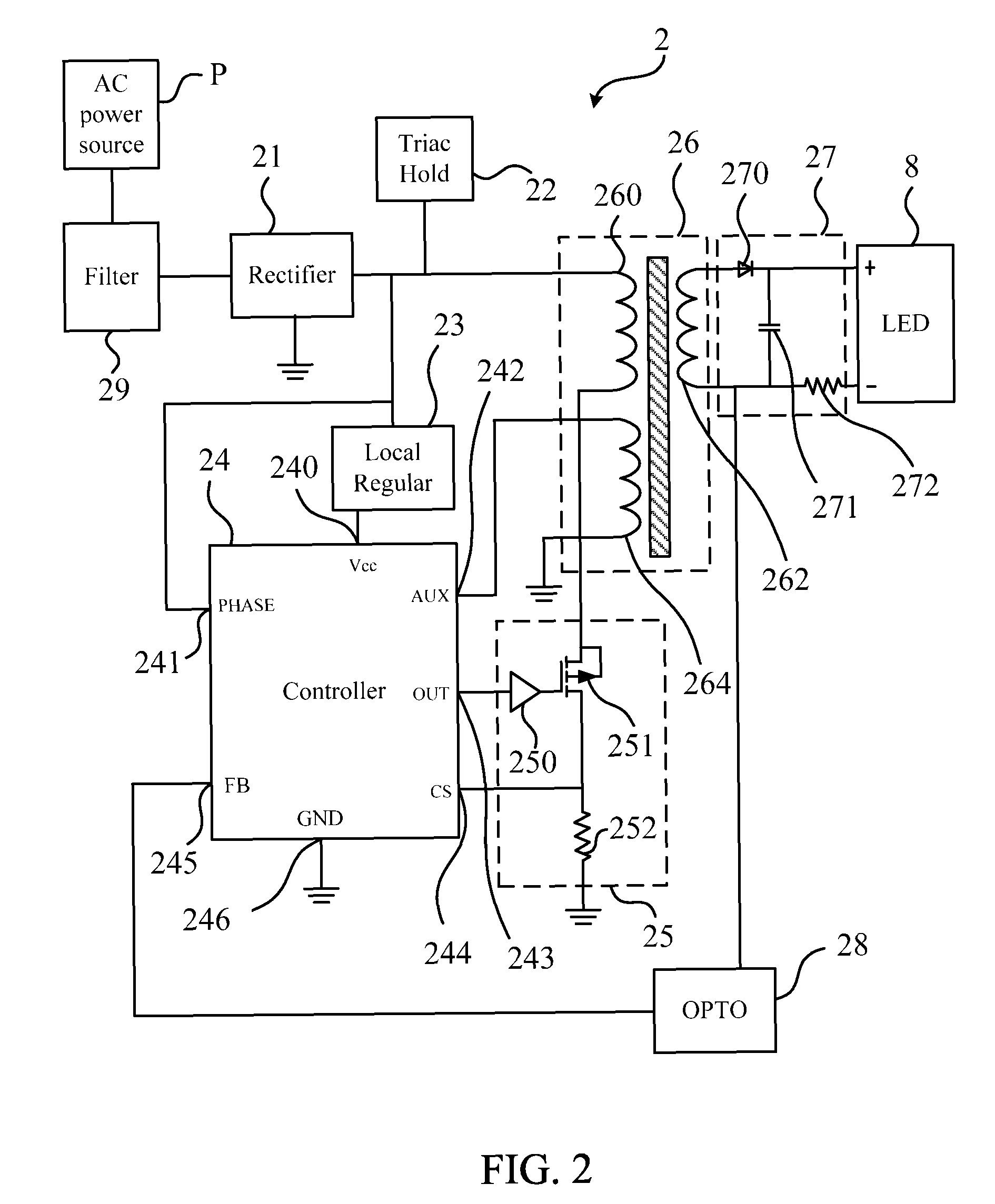
[0013]Please refer to FIG. 1. FIG. 1 is a schematic diagram illustrating a phase cut dimming LED driver 1 according to an embodiment of the invention. As shown in FIG. 1, the phase cut dimming LED driver 1 includes a rectifier 11, a phase cut hold 12, a local regulator 13, a controller 14, a power switch 15, a transformer 16, and a load detector 17.

[0014]In this embodiment, the rectifier 11 has rectifier inputs (terminal at left side of the rectifier 11) and a rectifier output (right side of the rectifier 11). The rectifier inputs are capable of being connected to an AC power source P to receive the power. The phase cut hold 12 is connected to the rectifier output of the rectifier 11, for processing the dimming functions. The local regulator 13 has a regulator input (up side of the local regulator 13) and a regulator output (down side of the local regulator 13). The regulator input is connected to the rectifier output of the rectifier 11, and also connected to the phase cut hold 12....


PUM


Abstract

A phase cut dimming LED driver includes a rectifier, a phase cut hold, a local regulator, controller, a power switch, a transformer, and a load detector. The phase cut hold is connected to the rectifier, one terminal of the primary winding of the transformer, and the local regulator. The controller includes pins connected to the local regulator, the power switch, and the aux winding of the transformer. The power switch is connected to the other terminal of the primary winding. The load detector is connected between the secondary winding of the transformer and a LED. The load detector sends the voltage or current signal of the LED to the controller, and the controller controls the power switch in an uninterrupted mode to keep the current or voltage in a condition to obtain higher PF and lower THD.

Description

FIELD OF THE INVENTION[0001]This invention relates to an AC phase cut dimming (phase cut dimmers can be triac leading edge, triac trailing edge, or IGBT types) dimming LED driver, and more particularly, to a phase cut dimming LED driver with high power factor (PF) and low total harmonic distortion (THD).BACKGROUND[0002]The illumination device is used at night or in situations where raising the level of illumination is desired. It consumes electrical power, and can be switched off in situations where enough illumination is present to save power. In some cases, such as at nightfall or a misty day, illumination is needed but the light from the illuminating device may be stronger than what is needed. In some cases the illumination device could be turned off to save power, however, in other cases the illumination device must be kept on, hence wasting power since the full intensity is generated. If the illumination of the light emitted by the illumination device is adjustable, it could be...

Claims


Application Information

Patent Timeline
Patent Type & Authority Patents(United States)
IPC IPC(8): H05B37/02H05B33/08H05B44/00
CPCH05B33/0851H05B33/0815H05B45/10H05B45/385
Inventor RHODES, JAMESWILKES, ARTHURBUSIER, MARK
Owner WARBIRD CAPITAL LLC
Why Eureka
Try Eureka