Power converter

a power converter and converter technology, applied in the direction of electric variable regulation, process and machine control, instruments, etc., can solve the problems of high undesirable effects, poor response of power factor pre-regulation circuits, and known power converters, and achieve fast override action and limited effectiveness

Active Publication Date: 2012-06-12
TEXAS INSTR INC
View PDF11 Cites 6 Cited by
  • Summary
  • Abstract
  • Description
  • Claims
  • Application Information

AI Technical Summary

Benefits of technology

[0005]It is an object therefore of the present invention to provide a power converter that overcomes at least some of the difficulties with the known constructions of power converters that is relatively simple and inexpensive to implement.STATEMENTS OF INVENTION
[0015]In one embodiment of the invention there is provided a power converter in which the control units means to measure circuit parameters of the power converter further comprises means to measure the current in the isolation stage output. This is seen as particularly useful as other implementations may be constrained in their effectiveness by time delays in the components used. By sensing the current in the isolation stage output, large transients of duration likely to cause an out of regulation condition may be handled in a quick and efficient manner and a fast override action is initiated by supplying additional current to the bulk capacitor. In this way, large transients may be handled effectively in the minimum time necessary keeping the power converter operating within its regulation parameters.

Problems solved by technology

Although relatively inexpensive and efficient to implement, there are however problems associated with the known power converters and in particular the known power factor pre-regulation circuits.
Accordingly, the transient response of these power factor pre-regulation circuits is inherently quite slow and therefore these power factor pre-regulation circuits tend to have a poor response to load transients.
This is seen as highly undesirable as a drop in the voltage of the bulk capacitor can often translate into a condition where a subsequent stage in the power converter will fall out of regulation and the voltage disturbance at the output of the power converter can be significant and more pronounced than was heretofore the case.
In addition to the above, these power factor pre-regulation circuits are relatively slow in responding to extra loads applied to the power converter.

Method used


Image

  • Power converter
  • Power converter

Examples


Embodiment Construction

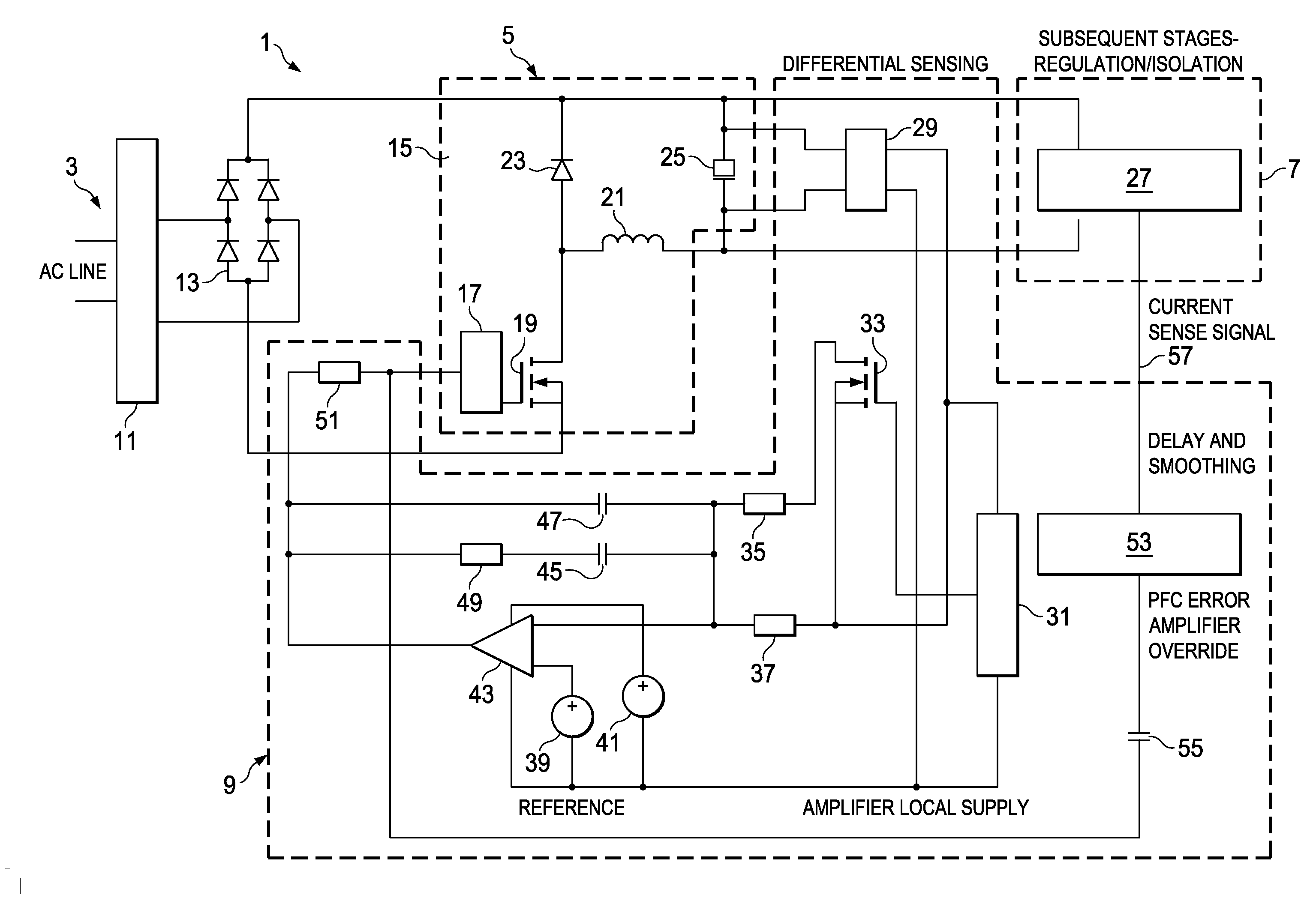
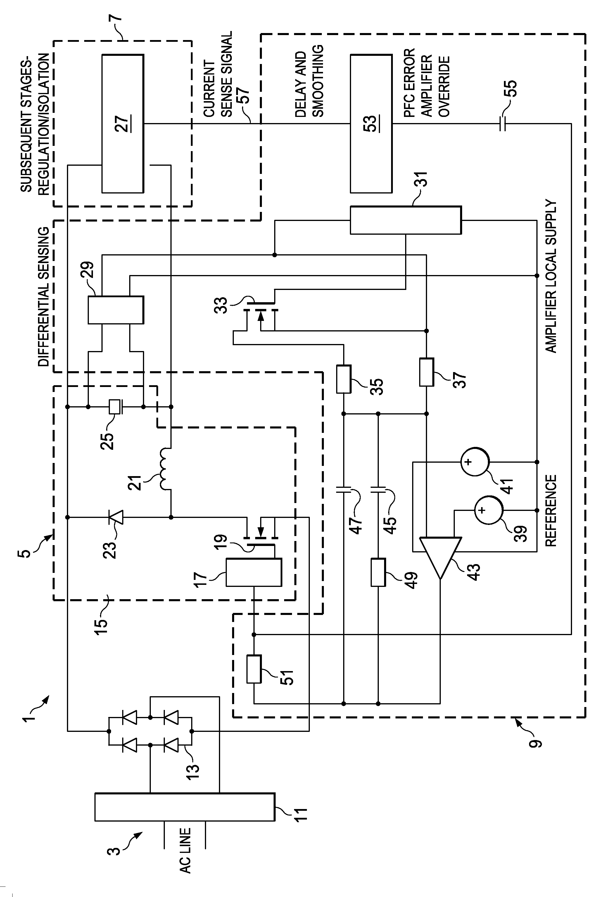
[0018]The invention will now be more clearly understood from the following description of an embodiment thereof, given by way of example only, with reference to the accompanying drawing, in which FIG. 1 is a circuit schematic of a power converter according to the present invention.

[0019]Referring to the drawing, there is shown a power converter, indicated generally by the reference numeral 1, comprising a converter input 3, a converter output (not shown), a power factor pre-regulation stage 5, an isolation stage 7 and a control unit 9. The power converter 1 further comprises an input filter 11 and an input bridge 13. The power factor pre-regulation stage 5 comprises a buck converter 15, which in turn comprises a buck controller 17, a buck switch 19, a buck inductor 21 and a buck diode 23. The buck converter 15 feeds a bulk capacitor 25. The isolation stage 7 comprises an isolation unit 27. The control unit 9 comprises a differential sensing circuit 29, a comparator 31 and a gain adj...


PUM


Abstract

This invention relates to a power converter (1) comprising a converter input (3), a converter output, a power factor pre-regulation stage (5), an isolation stage (7) and a control unit (9). The power factor pre-regulation stage (5) further comprises a buck power factor correction (PFC) circuit (15) and a bulk capacitor (25) fed by the buck PFC circuit. The amount of line current provided to the bulk capacitor (25) by the buck PFC circuit (15) may be adjusted according to the converter requirements in order to keep the voltage across the bulk capacitor (25) sufficient to ensure uniform operation of the power converter. Monitoring of the voltage across the bulk capacitor (25) and monitoring of the isolation stage (7) output current is provided to determine when additional current is to be applied to the bulk capacitor (25) and to ensure the power converter (1) operates within pre-defined parameters.

Description

[0001]This invention relates to a power converter comprising a converter input, a converter output, a power factor pre-regulation stage, an isolation stage and a control unit, the power factor pre-regulation stage further comprising a buck power factor correction (PFC) circuit implemented using low side drive and low side current sensing and a bulk capacitor, the buck PFC circuit supplying current to the bulk capacitor. More specifically, this invention relates to improvements in power converter front-end circuits.[0002]There are numerous different types and configurations of AC / DC power converters available on the marketplace. These AC / DC power converters transform the AC line voltage into a suitable DC voltage that may be used to power electronic circuits and electrical equipment. Typically, these AC / DC converters must be able to handle a wide AC voltage input range spanning Japanese low line voltage levels to European high line voltage levels. One of the more successful configura...

Claims


Application Information

Patent Timeline
Patent Type & Authority Patents(United States)
IPC IPC(8): G05F1/70
CPCG05F1/70H02M1/4208H02M2001/4291Y02B70/126Y02B70/10Y02P80/10H02M1/4291
Inventor YOUNG, GEORGE
Owner TEXAS INSTR INC
Why Eureka
Try Eureka