Apparatus and method for cooling engine coolant flowing through a radiator

a technology of radiator cooling and coolant flow, which is applied in the direction of mechanical equipment, machines/engines, mechanical energy handling, etc., can solve the problems of significant limitations of each method, the noise generated by the electrical generator during operation, and the electric generator can produce unwanted noise, etc., to reduce the noise of the fan, the effect of generating more noise and cost prohibitiv

Inactive Publication Date: 2006-09-07
GENERAC POWER SYSTEMS
View PDF2 Cites 7 Cited by
  • Summary
  • Abstract
  • Description
  • Claims
  • Application Information

AI Technical Summary

Benefits of technology

[0005] While these prior methods of minimizing the time period for rotating a fan of an engine-driven, electrical generator have been somewhat successful, each of these methods has significant limitations. By way of example, the use of a sensor and the associated electronics for selectively connecting the fan to the crankshaft of the engine can be cost prohibitive. Alternatively, by drawing air inward through the radiator as provided in various automotive applications, it has been found that the thermally responsive clutch interconnects the fan to the crankshaft at the engine for a longer period of time than is necessary to cool the engine coolant flowing through the radiator to a safe operating level. Hence, it can be appreciated that these prior art fan systems will generate more noise than necessary and / or desired by an end user.
[0006] Therefore, it is a primary object and feature of the present invention to provide a method and apparatus for reducing the fan noise associated with the operation of an engine driven, electrical generator.
[0007] It is a further object and feature of the present invention to provide a method and apparatus for reducing the fan noise associated with the operation of an engine driven, electrical generator that is simple and inexpensive to implement.
[0008] It is a still further object and feature of the present invention to provide a method and apparatus for reducing the fan noise associated with the operation of an engine driven, electrical generator that sufficiently cools the engine coolant flowing through the radiator of the electrical generator with the fan.
[0009] It is a still further object and feature of the present invention to provide a method and apparatus for sufficiently cooling the engine coolant flowing through the radiator of an engine for an engine-driven, electrical generator set that is adaptable for use with engines of different sizes.

Problems solved by technology

As is known, operation of an engine driven, electrical generator can produce unwanted noise.
The noise generated by the electrical generator during operation is often a result of the rotation of the fan used to cool the engine coolant flowing through the radiator tubes of the radiator of the electrical generator.
While these prior methods of minimizing the time period for rotating a fan of an engine-driven, electrical generator have been somewhat successful, each of these methods has significant limitations.
By way of example, the use of a sensor and the associated electronics for selectively connecting the fan to the crankshaft of the engine can be cost prohibitive.

Method used


Image

  • Apparatus and method for cooling engine coolant flowing through a radiator
  • Apparatus and method for cooling engine coolant flowing through a radiator
  • Apparatus and method for cooling engine coolant flowing through a radiator

Examples


Embodiment Construction

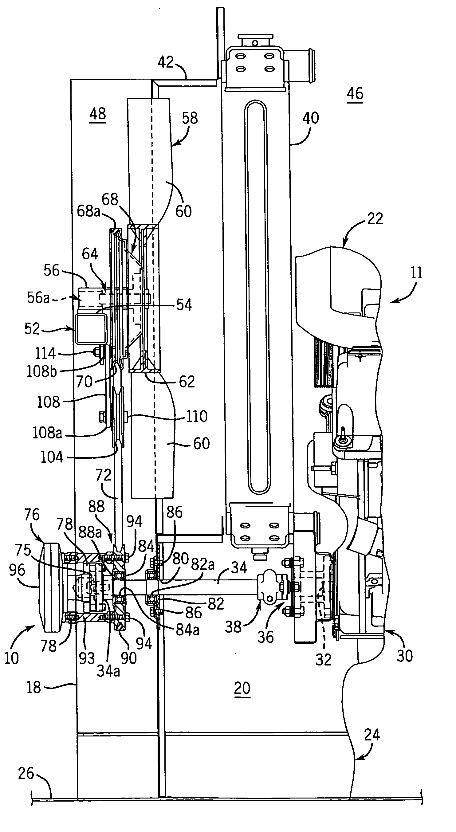
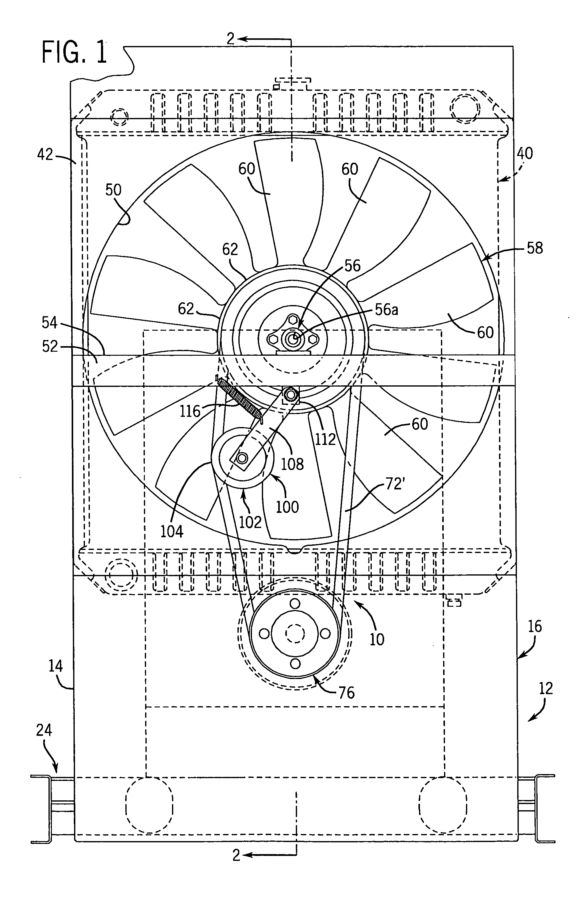
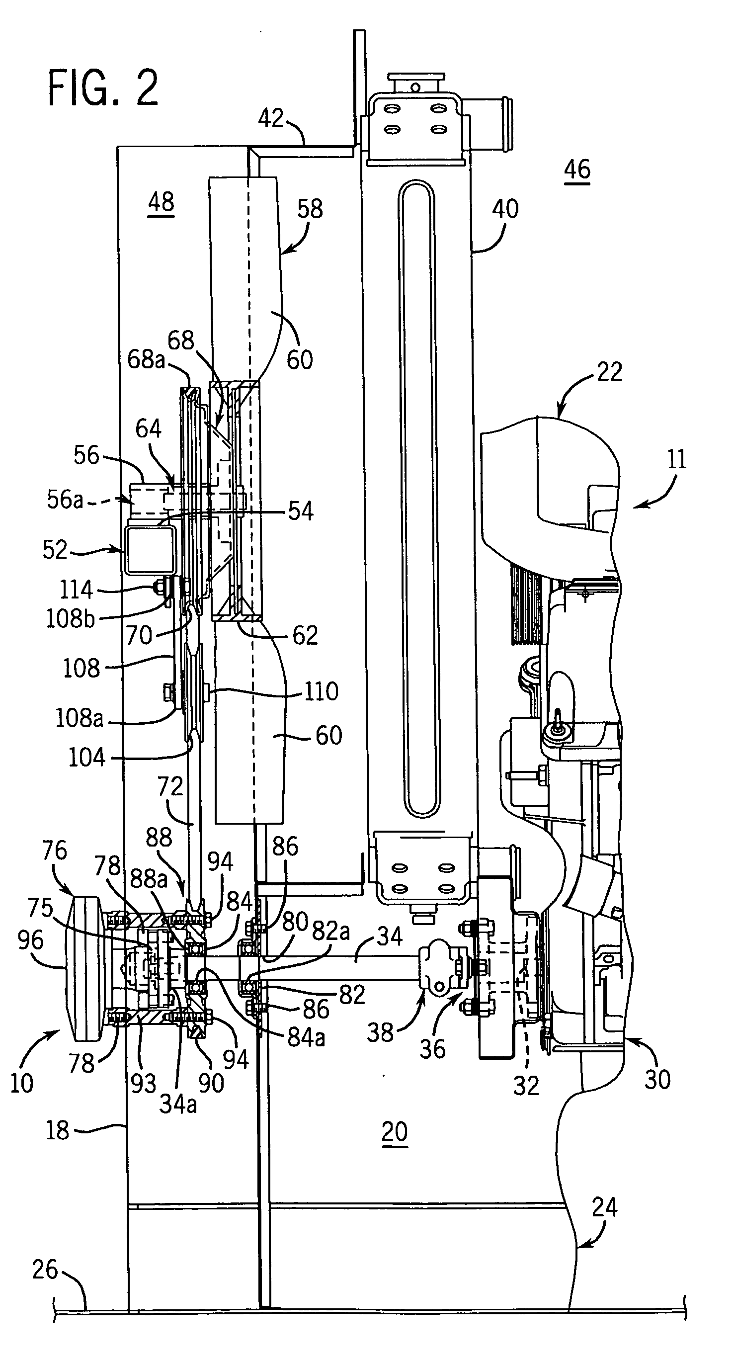
[0021] Referring to FIGS. 1 and 2, a fan drive assembly in accordance with the present invention is generally designated by the reference numeral 10. It is intended for fan drive assembly 10 to be used in connection with engine-driven, electrical generator set 11. As is conventional, generator set 11 is housed in enclosure 12 defined by first and second sidewalls 14 and 16, respectively, interconnected by a first forward end wall (not pictured) and a second rear end wall 18. Sidewalls 14 and 16 define interior 20 of enclosure 12. Base 24 of enclosure 12 is provided for supporting generator set 11 above a supporting surface 26 such as the ground, concrete slab or a mounting pad.

[0022] Generator set 11 includes an engine, generally designated by the reference numeral 30, which is supported within interior 20 of enclosure 12. As is conventional, engine 30 receives fuel such as diesel, natural gas or liquid propane vapor through an intake. The fuel is compressed and ignited within the ...


PUM


Abstract

An apparatus and method are provided for facilitating the cooling of engine coolant flowing through a radiator operatively connected to the engine of an engine-driven, electrical generator set. The engine has a crankshaft rotatable about a first axis and a radiator having a first side directed towards the engine and a second side. The apparatus includes a fan positionable on the second side of the radiator that is rotatable about a second axis generally parallel to and vertically spaced from the first axis. The apparatus includes a thermally responsive clutch having a driven portion. The clutch is movable between a first disengaged position wherein the driven portion is isolated from the crankshaft and a second engaged position wherein the driven portion rotates in unison with the crankshaft in response to a predetermined temperature. A fan drive system interconnects the driven portion of the clutch and the fan for translating rotation of the driven portion to the fan.

Description

FIELD OF THE INVENTION [0001] This invention relates generally to engine-driven, electrical generators, and in particular, to an apparatus and method for cooling the engine coolant flowing through a radiator of an engine-driven, electrical generator. BACKGROUND AND SUMMARY OF THE INVENTION [0002] Engine-driven, electrical generators are used in a wide variety of applications. Typically, such electrical generators utilize a single driving engine directly coupled to a generator or alternator through a common shaft. Upon actuation of the engine, the crankshaft thereof rotates the common shaft so as to drive the alternator which, in turn, generates electricity. It can be appreciated that since the engine and the alternator are housed in a single enclosure, a significant amount of heat is generated within the enclosure during operation of the electrical generator. [0003] Typically, prior electrical generators include radiators operatively connected to corresponding engines such that the ...

Claims


Application Information

Patent Timeline
Patent Type & Authority Applications(United States)
IPC IPC(8): H02K7/18F01P7/02F01N5/02F02B63/04
CPCF01P5/04F01P7/04F01P7/08F01P11/10F01P2025/13
Inventor KERN, ROBERT D.BAIRD, BRETGILLETTE, ALLEN D.ROLL, MICHAEL J.
Owner GENERAC POWER SYSTEMS
Why Eureka
Try Eureka