Large area, atmospheric pressure plasma for downstream processing

a technology of atmospheric pressure and plasma, applied in the direction of plasma technique, electric discharge lamp, coating, etc., can solve the problems of limited plasma use for treatment of commercially important substrates, complicated plasma treatment of these substrates using vacuum-based plasma, dangerous and prohibitively expensive, etc., to achieve rapid polymerization of monomer, uniform surface processing, and good results

Inactive Publication Date: 2013-01-29
APJET INC
View PDF53 Cites 20 Cited by
  • Summary
  • Abstract
  • Description
  • Claims
  • Application Information

AI Technical Summary

Benefits of technology

[0042]Material 28 may be moved perpendicular to the parallel alignment of the grounded electrode tubes, which provides a uniform, surface treatment because all areas of the surface are exposed to the gas flow. The gap between the material and the bottom of the tubes can also be controlled and varied. This gap is typically between about 0.5 mm and about 10 mm. A large gap enables the apparatus to polymerize monomer applied to the yarn of porous, thick substrates, such as deep-piled carpet, but also has the disadvantage that some of the active chemical species flowing out the plasma will recombine, or deactivate by other time-dependent means (such as by radiation or collisions), leading to slower processing. A small gap between the material and the tubes has the advantage of minimal deactivation of active species, but also is more prone to contaminating the plasma volume between the rf and ground electrodes by mixing of any volatile vapors from the material with the process gases. The ability to treat materials that may emit vapors from other processing steps, is a significant advantage of the present invention since treatment of such materials using any of the in-situ processing methods would result in contamination of the process gas by the emitted volatile vapor, or would require such high gas flow as to be prohibitive in cost. Close-spacing of the tubes also allows the plasma gas to exit towards the material at a higher velocity, because the gas flow is directed through a smaller space, which increases the linear velocity of the gas, but without a concomitant increase in gas consumption, and thereby operating cost.
[0043]If the workpiece or material were to be held static in the apparatus, the result would be stripes of treatment, each stripe corresponding to a gap between the grounded electrode tubes 24a-24d. By moving the workpiece across the apparatus in a uniform manner and in a direction normal to the ground electrodes, uniform surface processing has been achieved. This provides for continuous treatment of a material, either in an in-line process or a stand-alone batch process. Workpiece or material 28 may include flexible materials such as textiles, carpet, plastics, paper, metal films, and non-wovens, as examples, or rigid materials, such as glass, silicon wafers, metal and metal sheeting, wood, composite materials, cardboard, surgical instruments or skin, as examples. The workpiece may be a laminar material. The material may be moved using a conveyor belt, moving stage, or through other means of locomotion. Because the workpiece is outside of the plasma and the electrical fields therein, movement thereof is not complicated. The distance between the workpiece and the exit of the plasma-generated species between grounded electrode tubes 24a-24d is adjusted such that the deactivation or decay of the active species has not destroyed the chemical reactivity of the gas stream in the downstream region. Placement and movement of the workpiece between about 0 mm and about 10 mm from the surface of grounded electrode tubes 24a-24d, may satisfy this condition, depending on the process chemistry.
[0044]In surgical or cosmetic applications, such as facial peels or sterilization, apparatus 10 might be moved along the skin, allowing the active chemistry generated by the plasma to remove (by oxidation) the top layer of skin. For such procedures, an oxygen / helium feedgas chemistry might be employed, with a preferred mixture of about 1% oxygen in He. This gas mixture might also be employed for sterilization purposes and wound cleaning applications.
[0045]In summary, stable, non-arcing operation of the plasma requires three conditions to be satisfied: (a) a flow of a process gas consisting of between about 85% and about 100% helium; (b) rf excitation of one electrode in the frequency range of between about 1 MHz and about 100 MHz with bare metal electrodes exposed to the plasma; and (c) a gap between the rf-driven electrode and the ground electrode that is between approximately 0.5 mm and approximately 3 mm. It has been experimentally determined that good results are obtained at a spacing of about 1.6 mm when an rf frequency of about 13.56 MHz is employed (and at slightly smaller distances for higher frequencies). Additionally, low-temperature operation (that is, between about 0° C. and about 35° C.) requires efficient cooling of both electrodes using a temperature-controlled fluid, such as chilled air, ethylene glycol or distilled water, as examples. The use of conductive fluids, such as brine, is undesirable because of the corrosive effect of the brine as well as the electrical leakage of radiofrequency power that may result.
[0046]Vapor-condensation used to apply between an approximately 10 nm and an approximately 50 nm thickness of condensed perfluoroacrylate monomer to a fibrous substrate, as described in U.S. patent application Ser. No. 11 / 556,130, filed on Nov. 2, 2006, for “Treatment Of Fibrous Material Using Atmospheric Pressure Plasma Polymerization” by Gary S. Selwyn, the teachings of which are hereby incorporated by reference herein, can also be utilized in the present invention. Perfluoroacrylate monomer vapor entrained in a flow of inert or unreactive gas is directed into a heated applicator having a narrow slit or orifice opening to allow the gas stream and vapor to uniformly exit in the vicinity of a workpiece. Because the workpiece is at or below room temperature, as the material is moved past the applicator, a thin film of monomer or other chemical that is reactive to the plasma is uniformly condensed on the surface of the workpiece. The polymerization or activation of this condensed film may be achieved by exposure of the film to active chemical species created by the plasma and entrained in the gas stream exiting the plasma in accordance with the teachings of the present invention. The species exit the present apparatus through the narrow openings between the grounded electrode tubes and impinge on the condensed monomer, thereby rapidly polymerizing the monomer. The monomer is not exposed either to the plasma or to high-temperature chemical species. As described in EXAMPLE 3 hereinbelow, polymethylmethacrylate (PMMA) films on heat-sensitive substrates, such as polypropylene, have been made in this manner.
[0047]Associated with the vapor condensation procedure, it has been observed by the present inventor that the amount of open area of the plasma that is exposed to the workpiece (as an example, by a screen electrode) is inversely related to the efficacy of the process. That is, a grounded screen electrode, having open area of 60%, provides slow (tens of seconds) downstream polymerization of condensed monomer before the un-cooled screen electrode is heated by the plasma. This configuration was unable to be used for a continuously operating process because as the electrode screen (not water-cooled) heated up, the increasing neutral gas temperature caused the thinly condensed film to evaporate before it was able to be polymerized. This did not happen when the apparatus shown in FIGS. 1 and 2 hereof was used to generate the plasma. Applying the same conditions for two different tubular, water-cooled ground electrode of the present invention, and comparing the time required for monomer polymerization, shows that a 0.12 in. gap between tubes provides 28.8% open area of the plasma, but results in a polymerization rate that is about 25% slower than a 0.09 in. gap between tubes, having only 23.4% open area. The faster polymerization rate of the smaller gap may be attributed to the higher linear gas flow resulting from a smaller opening. There is also an enhancement from the hollow cathode effect that causes a glow to form between the tubes, if the gap is adjusted to an optimal spacing.

Problems solved by technology

Treatment of these substrates using vacuum-based plasmas would be complicated, dangerous and prohibitively expensive.
The present state of the art for plasmas operating at or near atmospheric pressure also limits the use of plasma for treatment of these commercially-important substrates.
However, since electrical power must be transmitted through the dielectric cover, the power density that a DBD discharge can achieve is limited.
Low power density typically produces slow processing, because low-power density in the plasma also results in a slow generation rate of the active, chemical species responsible for materials processing.
Again, slow processing speed and inability to cool the neutral gas temperature are characteristic of these discharges, and processing is limited to the treatment of dry, non-conductive substrates.
There is no effective way to water-cool a wire electrode, because the means of plasma generation depends on the strong electric field created by a small radius of curvature.
Further, the use of a dielectric cover on the electrode of the micro-hollow discharge reduces the ability to effectively cool the neutral gas temperature by water cooling of the electrodes, because thermal conduction is inhibited by the presence of the dielectric.
Another problem for large area processing, is that the active treatment region is limited to the open area provided by each of the micro-hollow discharge elements.
Further, the metal screen cannot be water-cooled, leading to a high, neutral gas temperature (>150° C.
), especially if high rf power is used since heat removal is limited to conduction at the point of contact with the housing, and from the heat capacity of the gas as it exits the plasma.
A plasma torch is a thermal discharge characterized by generation of extremely high temperatures, often in excess of 10,000° C., which is destructive to substrates.

Method used


Image

  • Large area, atmospheric pressure plasma for downstream processing
  • Large area, atmospheric pressure plasma for downstream processing
  • Large area, atmospheric pressure plasma for downstream processing

Examples


example 1

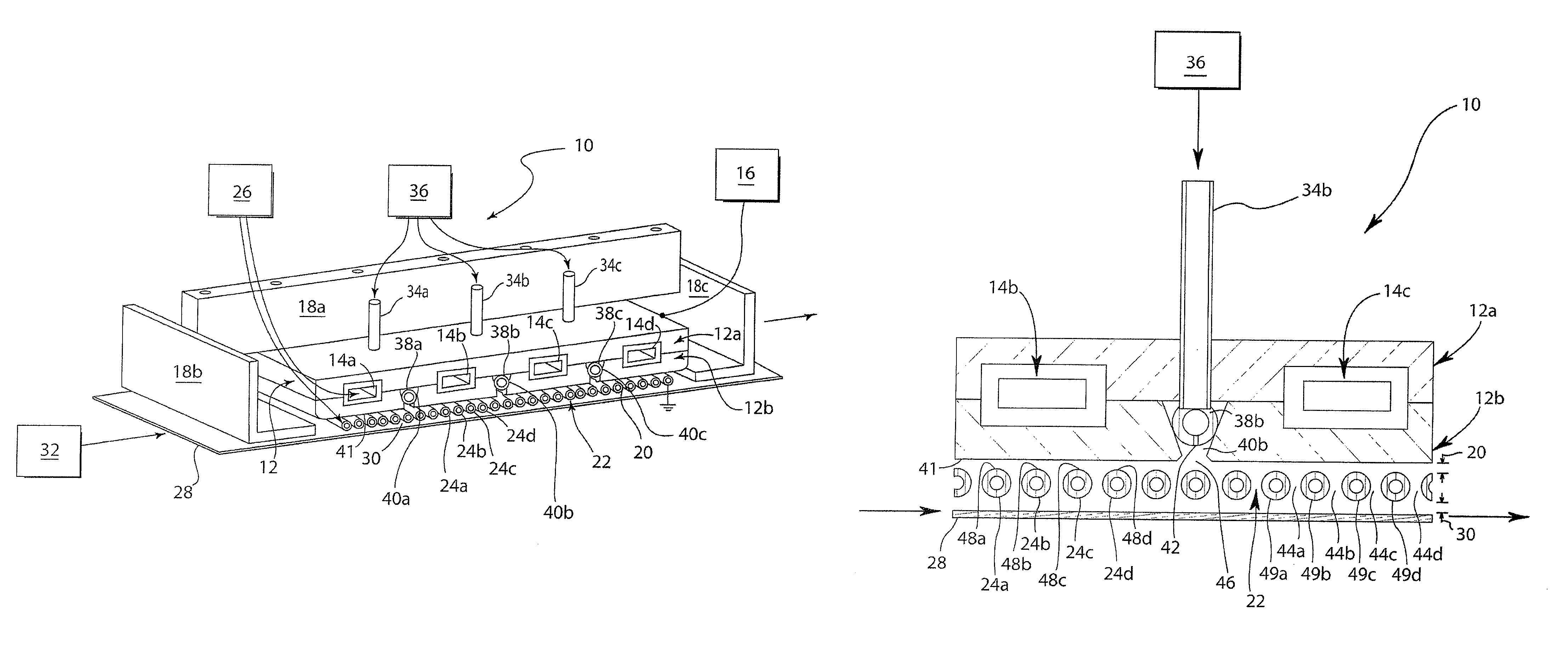
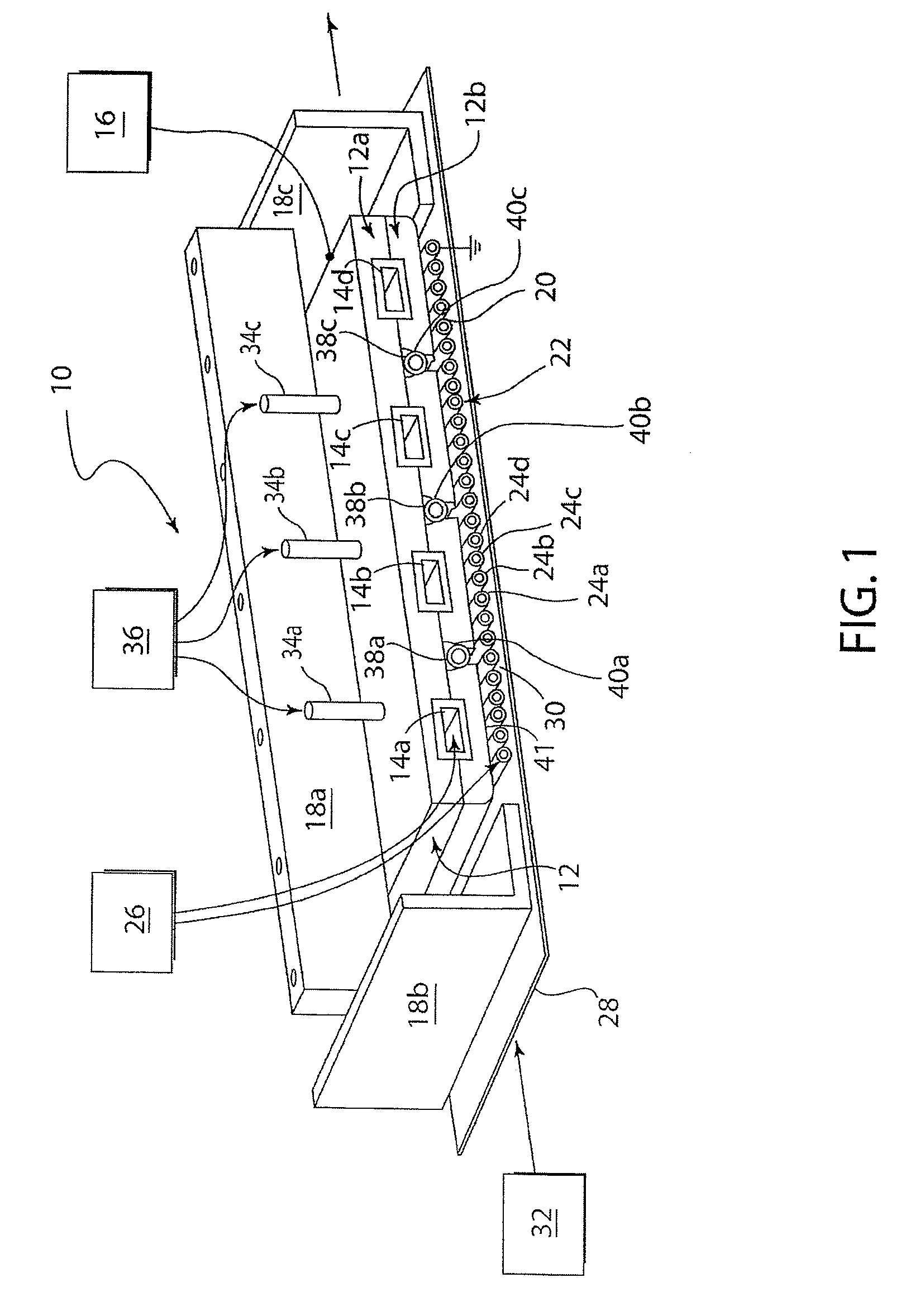
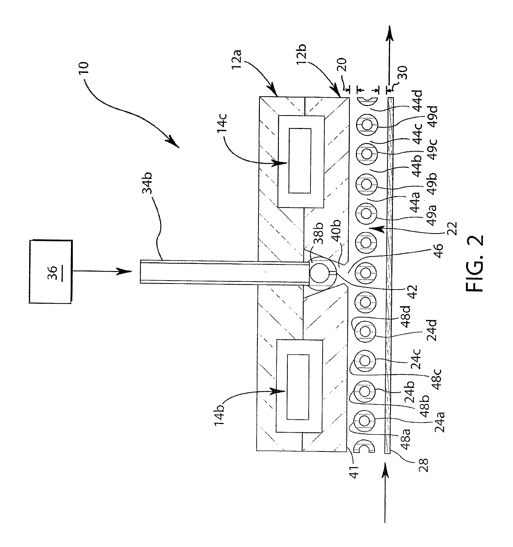
[0050]A polyester fabric having a thickness of 0.7 mm. was mounted on a movable, temperature-controlled stage, the temperature set at 15° C., and the fabric plasma-treated for water and oil repellence (hydrophobicity and oleophobicity) in accordance with the teachings of the patent application Ser. No. 11 / 556,130, supra. The gap between the applicator and the stage was 3.5 mm; the gap between the planar rf electrode and the top of the ground electrode was 2.0 mm; the grounded, water-cooled, parallel, aluminum tubes, ¼ in. O.D. had a spacing between the tubes of 0.09 in.; and the gap between the bottom of the ground electrode and the stage was 5.2 mm. The argon flow into the evaporator / applicator was 0.3 slpm, and the chemical feed rate of perfluorooctylacrylate-based monomer (Daikin TG-10) was 0.6 ml / min. The temperature of the evaporator was 170° C. and that for the applicator was 180° C. The plasma was operated at 650 W at 13.56 MHz using a constant flow of 40 slpm of He, to which...

example 2

[0054]A similar sample to that described in EXAMPLE 1 hereof was mounted on a movable, temperature-controlled stage, the temperature set at 15° C., and plasma-treated for water and oil repellence (hydrophobicity and oleophobicity) in accordance with the teachings of the patent application Ser. No. 11 / 556,130, supra. The distance between the applicator and the stage surface to which the fabric was mounted was 3.5 mm; the gaps between the planar rf electrode and the tops of the ¼ in. O.D. tubular, aluminum grounded electrodes were 2.0 mm; and the gap between the bottom of the tubular ground electrode and the stage was 2.5 mm. The argon flow through the evaporator / applicator was 0.3 slpm; the total flow through the three gas distribution tubes connected to the 12 in.×5 in. rf electrode was comprised of 40 slpm He+0.04 slpm of NH3; the applied rf power was 700 W at 13.56 MHz. The stage speed was 3.3 yd / min., and a perfluorooctylacrylate-based monomer (Daikin TG-10) was applied at a flow...

example 3

[0056]A transparent, 0.05 mm thick polypropylene film was mounted on a movable, temperature-controlled stage, the temperature set at 15° C., and a thinly-condensed film of liquid methylmethacrylate (MMA) monomer was applied to the surface facing the downstream plasma at a flow rate of 0.4 ml / min., in accordance with the teachings of the U.S. patent application Ser. No. 11 / 556,130, supra. The argon flowrate through the evaporator / applicator was 0.3 slpm, the distance between the applicator and the stage surface to which the film was mounted was 3.0 mm, the temperature of the evaporator was 95° C., and that for the applicator was 100° C.

[0057]In the plasma discharge apparatus of the present invention, both the gaps between the planar rf electrode and the closest locations of the surfaces of the ¼ in. O.D. tubular, aluminum grounded electrodes thereto, and the spacings between the surfaces of the tubular electrodes were 2.0 mm; and the gaps between the closest locations of the surfaces...


PUM

PropertyMeasurementUnit
temperatureaaaaaaaaaa
gas temperatureaaaaaaaaaa
temperaturesaaaaaaaaaa

Abstract

An arcless, atmospheric-pressure plasma generating apparatus capable of producing a large-area, temperature-controlled, stable discharge at power densities between about 0.1 W / cm3 and about 200 W / cm3, while having an operating gas temperature of less than 50° C., for processing materials outside of the discharge, is described. The apparatus produces active chemical species, including gaseous metastables and radicals which may be used for polymerization (either free radical-induced or through dehydrogenation-based polymerization), surface cleaning and modification, etching, adhesion promotion, and sterilization, as examples. The invention may include either a cooled rf-driven electrode or a cooled ground electrode, or two cooled electrodes, wherein active components of the plasma may be directed out of the plasma and onto an external workpiece without simultaneously exposing a material to the electrical influence or ionic components of the plasma.

Description

FIELD OF THE INVENTION[0001]The present invention relates generally to apparatus and method for plasma processing of materials and, more particularly, to an atmospheric-pressure plasma generating apparatus capable of producing a temperature-controlled, stable discharge having a temperature of less than 50° C. for generation of active chemical species, including gas metastable and radical species effective for large area plasma processing, whereby active chemical or active physical components of the plasma exit the discharge and impinge on a substrate disposed externally to the discharge, without simultaneous exposure of the substrate to the electrical influence or ionic components of the plasma.BACKGROUND OF THE INVENTION[0002]The use of ionized gases (plasma) for treating, modifying and etching of material surfaces is well established. Both vacuum-based plasmas and those that operate at or near atmospheric pressure, have been used for surface modification of materials ranging from ...

Claims


Application Information

Patent Timeline
Patent Type & Authority Patents(United States)
IPC IPC(8): C23C16/00H01L21/00
CPCH01J37/32082H01J37/32357H05H1/46H01J37/32825H05H1/24H01J37/32596H05H1/2431H05H1/2418H05H1/4697
Inventor SELWYN, GARY S.
Owner APJET INC
Why Eureka
Try Eureka