Electronic device housing

a technology for electronic devices and housings, applied in the direction of electric apparatus casings/cabinets/drawers, gaseous cathodes, gas-filled discharge tubes, etc., can solve the problems of not being able to repel dust and sweat, and not self-cleaning of metal appearance coatings

Inactive Publication Date: 2011-06-30
SHENZHEN FUTAIHONG PRECISION IND CO LTD +1
View PDF3 Cites 26 Cited by
  • Summary
  • Abstract
  • Description
  • Claims
  • Application Information

AI Technical Summary

Problems solved by technology

However, the metallic-appearing coatings are not self-cleaning, and cannot repel dust and sweat that collects on the electronic device housings, nor can they resist fingerprint thereon.

Method used


Image

  • Electronic device housing
  • Electronic device housing

Examples


Embodiment Construction

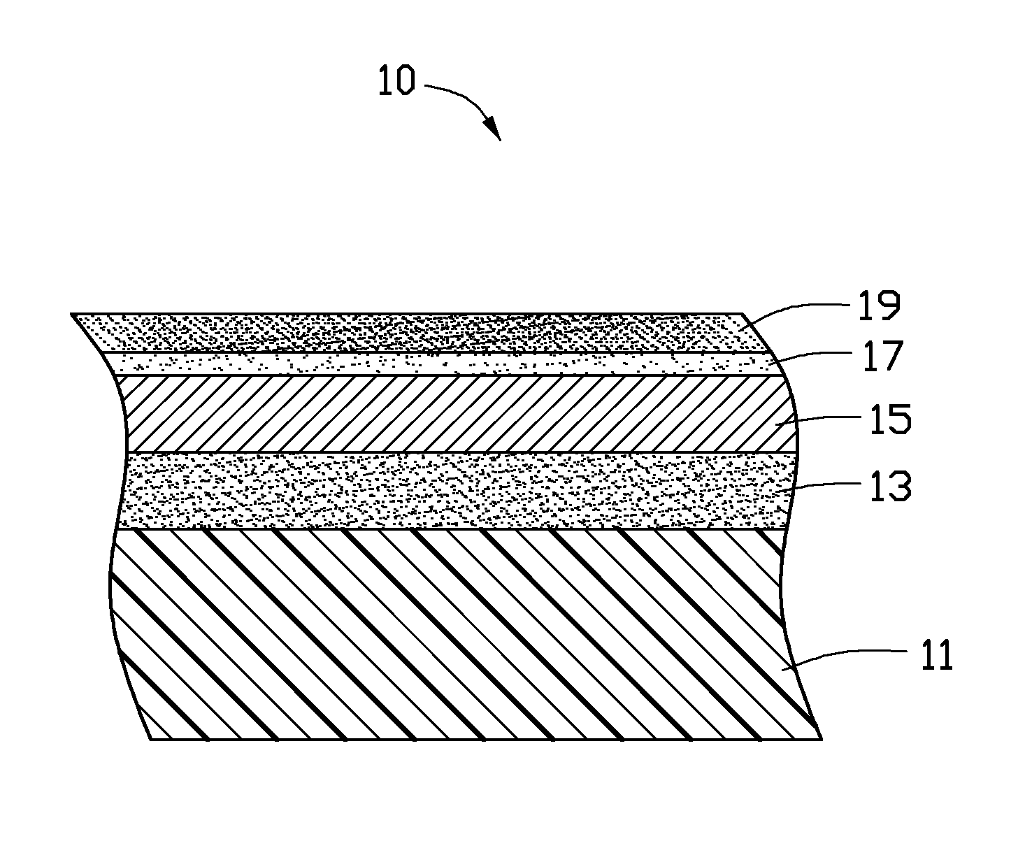
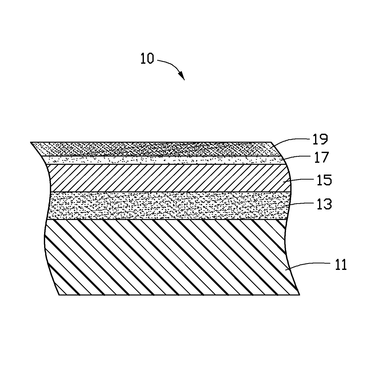
[0009]The FIGURE shows an electronic device housing 10 according to an embodiment. The electronic device housing 10 includes a substrate 11, and a base paint coating 13, a metallic-appearing coating 15, an intermediate paint coating 17, and a top coating 19 formed on a surface of the substrate 11 in that order. The electronic device housing 10 may be a housing of a mobile phone, PDA, note book computer, MP3, MP4, GPS navigator, or digital camera.

[0010]The substrate 11 may be formed by molding one or more of polycarbonate (PC), polyethylene (PE), polymethyl methacrylate (PMMA), and a mixture of polycarbonate and acrylonitrile-butadiene-styrene plastics (PC+ABS). The substrate 11 may instead be made of glass or ceramic.

[0011]The base paint coating 13 may be formed by spraying acrylic resin paint, and can be transparent. The base paint coating 13 has a smooth surface for enhancing bonding between the base paint coating 13 and subsequent coatings. The base paint coating 13 has a thickne...


PUM


Abstract

An electronic device housing is provided. The electronic device housing includes a substrate, a metallic-appearing coating formed on the substrate, and a top coating formed on the metallic-appearing coating. The top coating contains nano-titanium dioxide powder and fluorocarbon resin. The electronic device housing has self-cleaning and anti-fingerprint properties.

Description

CROSS-REFERENCE TO RELATED APPLICATIONS[0001]This application is one of the three related co-pending U.S. patent applications listed below. All listed applications have the same assignee. The disclosure of each of the listed applications is incorporated by reference into all the other listed applications.AttorneyDocket No.TitleInventorsUS 31521ELECTRONIC DEVICE HOUSINGQI-JIAN DU et al.AND METHOD FOR MAKINGTHE SAMEUS 31523ELECTRONIC DEVICE HOUSINGQI-JIAN DU et al.US 31998ELECTRONIC DEVICE HOUSINGQI-JIAN DU et al.BACKGROUND[0002]1. Technical Field[0003]The present disclosure relates to electronic device housings, particularly to an electronic device housing having self-cleaning and anti-fingerprint properties.[0004]2. Description of Related Art[0005]Decorative metallic-appearing coatings are often formed on housings of electronic devices. The metallic-appearing coatings are typically formed by vacuum deposition to provide a metallic-appearance. The metallic-appearing coatings formed b...

Claims


Application Information

Patent Timeline
Patent Type & Authority Applications(United States)
IPC IPC(8): H05K5/04
CPCB32B37/24B32B2037/243H04M1/0283B32B2038/0092B32B2309/105B32B2037/246
Inventor DU, QI-JIANCHIANG, CHWAN-HWA
Owner SHENZHEN FUTAIHONG PRECISION IND CO LTD
Why Eureka
Try Eureka