Bone fixation system with curved profile threads

a technology of bone fixation and profile threads, which is applied in the field of bone fasteners, can solve the problems of affecting the screwing effect of the fastener, the inclination of the thread head of the fastener, and the damage of the threaded hole, so as to facilitate the screwing

a technology of bone fixation and profile threads, which is applied in the field of bone fasteners, can solve the problems of affecting the screwing effect of the fastener, the inclination of the thread head of the fastener, and the damage of the threaded hole, so as to facilitate the screwing

US20110218580A1Inactive Publication Date: 2011-09-08STRYKER EURO OPERATIONS HLDG LLC

Image

  • Bone fixation system with curved profile threads
  • Bone fixation system with curved profile threads
  • Bone fixation system with curved profile threads

Examples


Embodiment Construction

stener embodiment;

[0027]FIG. 5 is a detailed view of peaks of the thread of the bone fastener head shown in FIGS. 2 and 4;

[0028]FIG. 6 is a cross-sectional view of the screw head shown in FIGS. 1 and 3;

[0029]FIG. 7 is a cross-sectional view of a screw head shown in FIGS. 2 and 4;

[0030]FIG. 8 is a detailed view of another screw head embodiment;

[0031]FIG. 9 is a detailed view of another screw head embodiment;

[0032]FIG. 10 is a cross-sectional view of a dummy implant embodiment;

[0033]FIG. 11 is a side view of another dummy implant embodiment;

[0034]FIG. 11A is a top view of the plate of FIG. 11 and;

[0035]FIG. 12 is a cross-sectional view of the implant shown in FIG. 11.

DETAILED DESCRIPTION

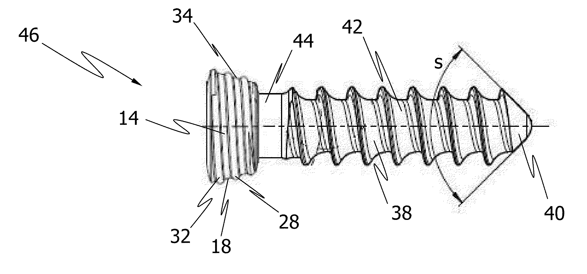
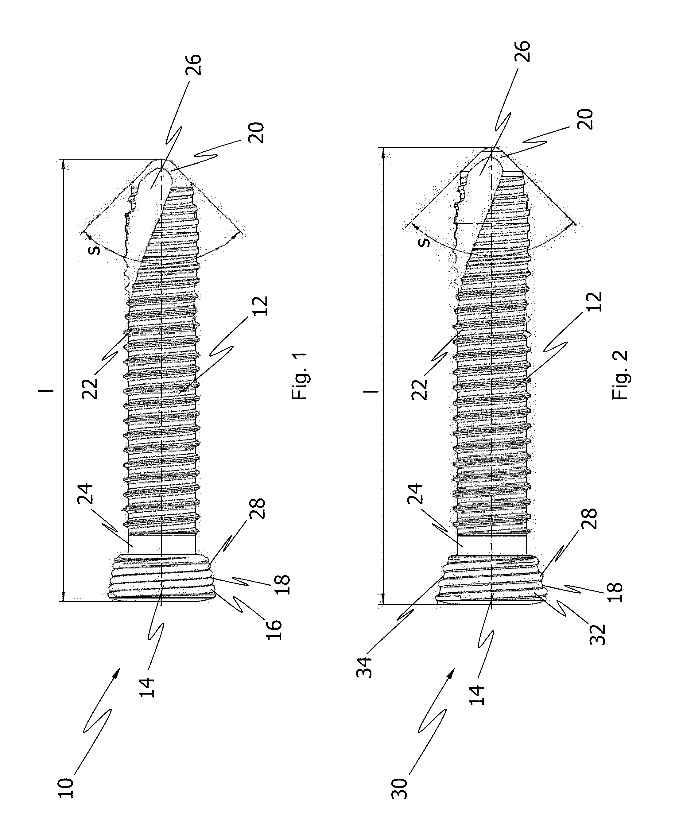
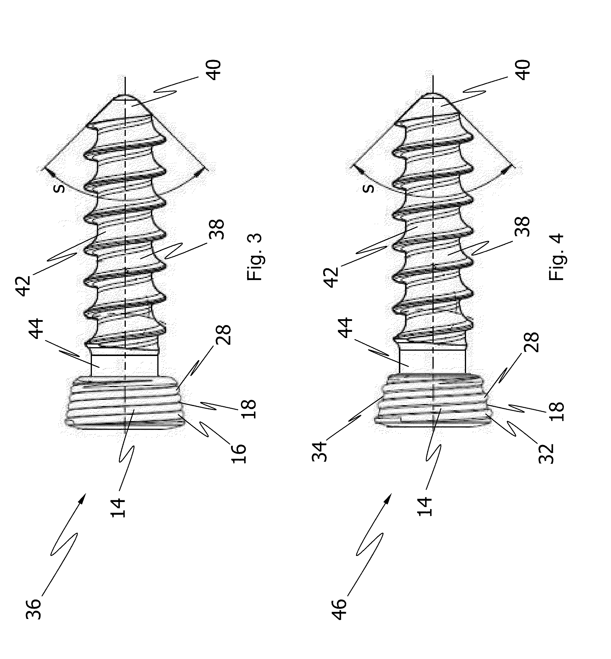
[0036]Referring to FIG. 1 shown, there is shows a side view of a first embodiment of a bone fastener in the form of a bone screw 10 for use as a locking screw in orthopedic surgery for fixing an implant (not shown in FIG. 1) to bone. The bone screw 10 comprises a shaft 12 configured to engage bone and ...


PUM


Abstract

A bone fastener for use in orthopedic surgery for fixing an implant to bone has a threaded or unthreaded shaft configured to engage bone and a head having a thread on an outer surface to engage the implant. The thread on the head of the fastener has a profile in cross section that includes peaks with a curved shape.

Description

BACKGROUND OF THE INVENTION[0001]The present disclosure generally relates to a bone fastener such as a bone screw or bone peg for use in orthopedic surgery, preferably for fixing an implant such as a bone plate to bone. The disclosure further relates to an implant system for fixation of bone.[0002]Bone screws are available in a plurality of variations for different applications. Bone screws which can be secured to a bone plate or a similar implant are also known as locking screws. For locking the bone screw to the bone plate, a head of the bone screw is provided with a thread that mates with a corresponding thread on an inner surface of a plate hole.[0003]U.S. Patent Publication Nos. 2005 / 0277937 and 2009 / 0192550 relate to a typical locking screw which is intended to be secured to a bone plate. The head of the bone screw has a spherical shape and a thread with V-shaped ridges. The thread of the head is a double lead thread which mates with an internal thread of a plate hole. The rid...

Claims


Application Information

Patent Timeline
08 Sep 2011
Publication
US20110218580A1
IPC
A61B17/86
CPC
A61B17/86; A61B17/8057; A61B17/8605; A61B17/863
Inventors
SCHWAGER, MANUEL; WIRTH, RENE