Heat pump system

a heat pump and system technology, applied in heat pumps, lighting and heating apparatus, heating types, etc., can solve problems such as failure to achieve desired operation, complicated operation of four-way switching valves, and possible operation errors, and achieve the effect of preventing the thermoregulation mod

Active Publication Date: 2011-12-15
DAIKIN IND LTD
View PDF13 Cites 15 Cited by
  • Summary
  • Abstract
  • Description
  • Claims
  • Application Information

AI Technical Summary

Benefits of technology

[0037]It is thereby possible with this heat pump system to prevent the thermoregulation mode from being switched frequently.

Problems solved by technology

However, since users simply recognize such a heat pump system as being both an air-cooling and air-warming apparatus and a hot water supply apparatus, users fail to recognize the necessity of operating the four-way switching valve and forget to operate the four-way switching valve, operational mistakes may occur, and operating the four-way switching valve is complicated.
Thus, in a heat pump system in which a usage unit for performing a hot-water supply operation of heating an aqueous medium and a usage unit for performing cooling and heating of an air medium are connected to a shared heat source unit, not only must the usage units themselves be operated, but the switched state of the four-way switching valve, which is the thermoregulation mode of the entire system, must be switched as well; therefore, there is a risk that the desired operation will not be successfully performed due to the operation being complicated, the switching of the thermoregulation mode being forgotten, or mistakes in the switching.

Method used


Image

  • Heat pump system
  • Heat pump system
  • Heat pump system

Examples


first embodiment

Configuration

[0046]—Overall Configuration—

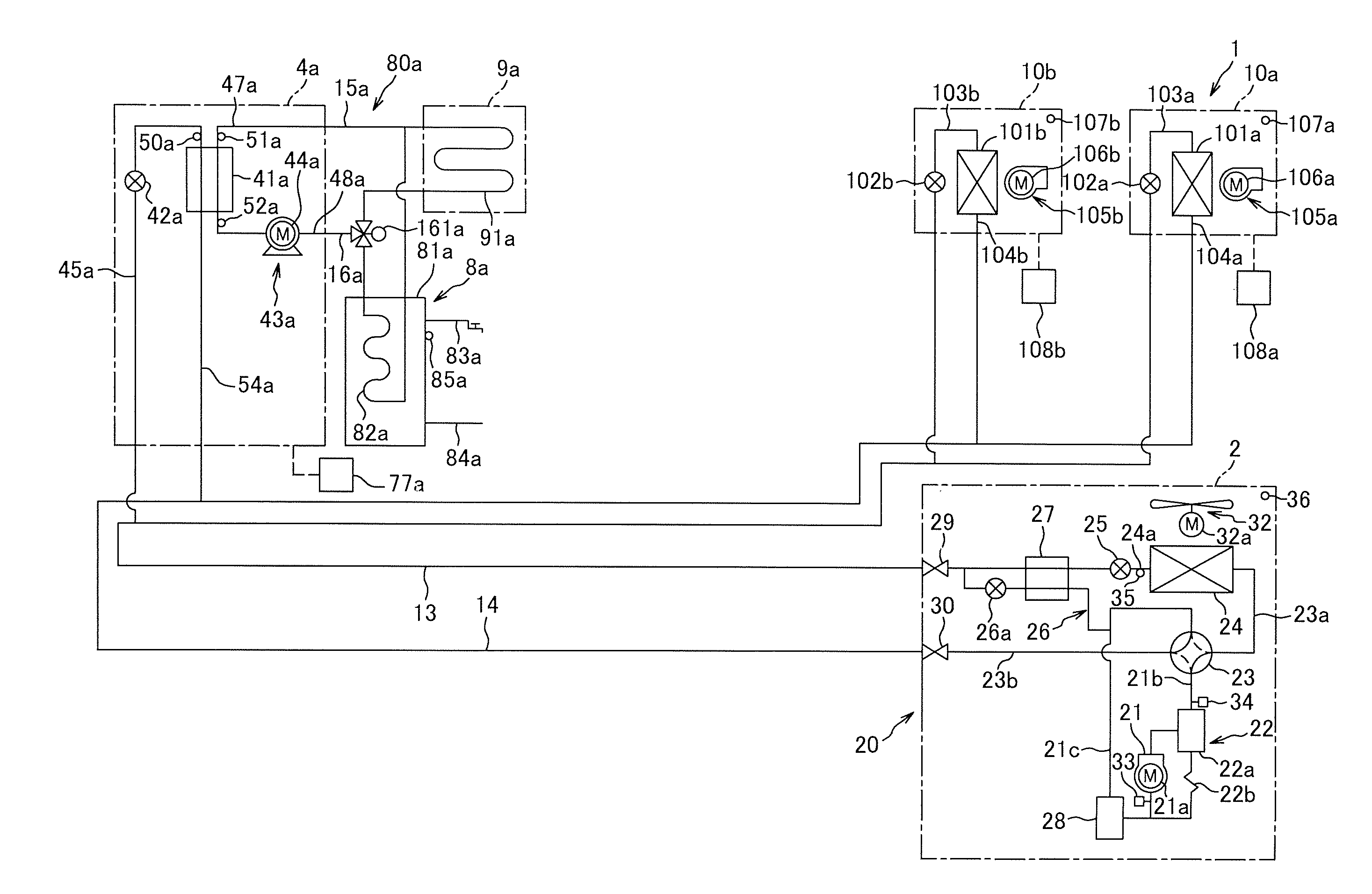
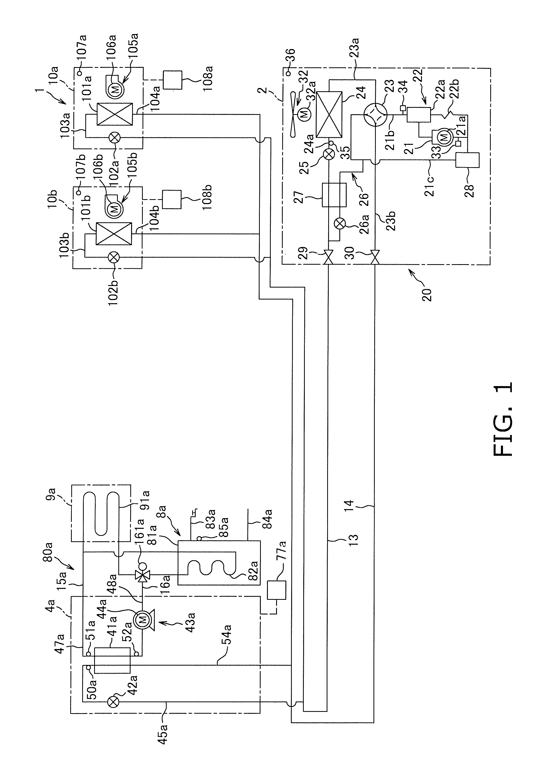
[0047]FIG. 1 is a view showing the general configuration of a heat pump system 1 according to a first embodiment of the present invention. The heat pump system 1 is an apparatus capable of operation for heating an aqueous medium, and other operation by utilizing a vapor compression heat pump cycle.

[0048]The heat pump system 1 comprises primarily a heat source unit 2, a first usage unit 4a, second usage units 10a, 10b, a liquid refrigerant communication tube 13, a gas refrigerant communication tube 14, a hot-water storage unit 8a, a hot-water air-warming unit 9a, an aqueous medium communication tube 15a, and an aqueous medium communication tube 16a; wherein the heat source unit 2, the first usage unit 4a, and the second usage units 10a, 10b are connected via the liquid refrigerant communication tubes 13, 14, thereby constituting a heat-source-side refrigerant circuit 20; and the first usage unit 4a, the hot-water storage unit 8a, and the hot-...

second embodiment

[0162]In the heat pump system 1 in the first embodiment described above, operation must be carried out under conditions in which the pressure of the heat-source-side refrigerant in the discharge of the heat-source-side compressor 21 is increased, or under other poor conditions in order to obtain a high-temperature aqueous medium such as hot water at, e.g., 65° C. or higher, and such an operation is not regarded as a preferred operation.

[0163]In view of the above, with the heat pump system 200, the first usage-side heat exchanger 41a in the configuration of the heat pump system 1 in the first embodiment described above (see FIG. 1) is a heat exchanger for exchanging heat between the heat-source-side refrigerant introduced from the gas refrigerant communication tube 14 and the usage-side refrigerant, which is separate from the heat-source-side refrigerant; and the first usage unit 4a is further provided with a usage-side compressor 62a (described hereinafter) for compressing the usage...

third embodiment

[0212]In the heat pump system 1 in the first embodiment described above (see FIG. 1), since the air-cooling operation of the second usage units 10a, 10b cannot be performed together with the hot-water supply operation of the first usage unit 4a, if it were possible to perform such an operation (hereinbelow referred to as the “exhaust heat hot-water supply operation”), it would also be possible to perform a hot-water supply operation according to the heat radiation load (i.e. the hot-water supply load) in the first usage-side heat exchanger 4a that is proportionate to the evaporation load (i.e. the air-cooling load) in the second usage-side heat exchangers 101a, 101b in an operation state such as summer when the air-cooling operation is performed, which would be preferable in terms of conserving energy.

[0213]In view of this, the heat pump system 300 has the configuration of the heat pump system 1 according to the first embodiment described above (see FIG. 1), wherein an exhaust heat ...


PUM


Abstract

A heat pump system includes a first usage unit operable to perform a hot-water supply operation to heat an aqueous medium and a second usage unit operable to perform air-cooling and air-warming operations to cool or heat an air medium. The first and second usage units are both connected to a heat source unit in such a manner that the first and second usage units are incapable of individually selecting and performing a hot-water supply operation, an air-cooling operation, or an air-warming operation. The heat pump system is capable of switching operation to a thermoregulation mode different from the switched state of a heat-source-side switching mechanism in response to a thermoregulation mode command issued by a first usage-side controller, a second usage side controller or a centralized controller.

Description

TECHNICAL FIELD[0001]The present invention relates to a heat pump system, and particularly relates to a heat pump system in which a usage unit for performing a hot-water supply operation of heating an aqueous medium and a usage unit for performing cooling and heating of an air medium are connected to a shared heat source unit.BACKGROUND ART[0002]In the past, there have been heat pump-type hot-water floor heating apparatuses such as the one disclosed in Patent Literature 1 (Japanese Laid-open Patent Publication No. 2000-46417), which has a hot water heat exchanger connected to a floor heating panel and an indoor heat exchanger for performing indoor air-warming. Such a heat pump-type hot-water floor heating apparatus is configured primarily by connecting both a hot water heat exchanger and an indoor heat exchanger to a shared compressor, a four-way switching valve, an outdoor heat exchanger, and other components.SUMMARY OF THE INVENTION[0003]Consideration has been given to using the a...

Claims


Application Information

Patent Timeline
Patent Type & Authority Applications(United States)
IPC IPC(8): F25B30/00
CPCF24D3/08F24D3/18F24D2200/12F24H6/00F25B7/00F25B13/00Y02B30/12F25B2313/003F25B2313/006F25B2313/007F25B2313/0231F25B2313/02741F25B29/003
Inventor HONDA, MASAHIRO
Owner DAIKIN IND LTD
Why Eureka
Try Eureka