
Mouthguard having breathing cavities and breathing holes incorporated into the body of the mouthguard

a mouthguard and breathing hole technology, applied in the field of mouthguards, can solve the problems of athletes not being able to breathe through their mouths

Inactive Publication Date: 2012-01-26
JR286 TECH
View PDF8 Cites 31 Cited by
  • Summary
  • Abstract
  • Description
  • Claims
  • Application Information

AI Technical Summary

Benefits of technology

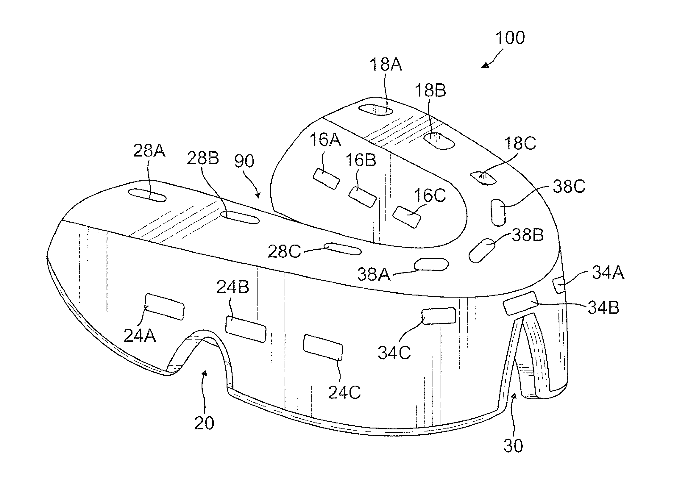
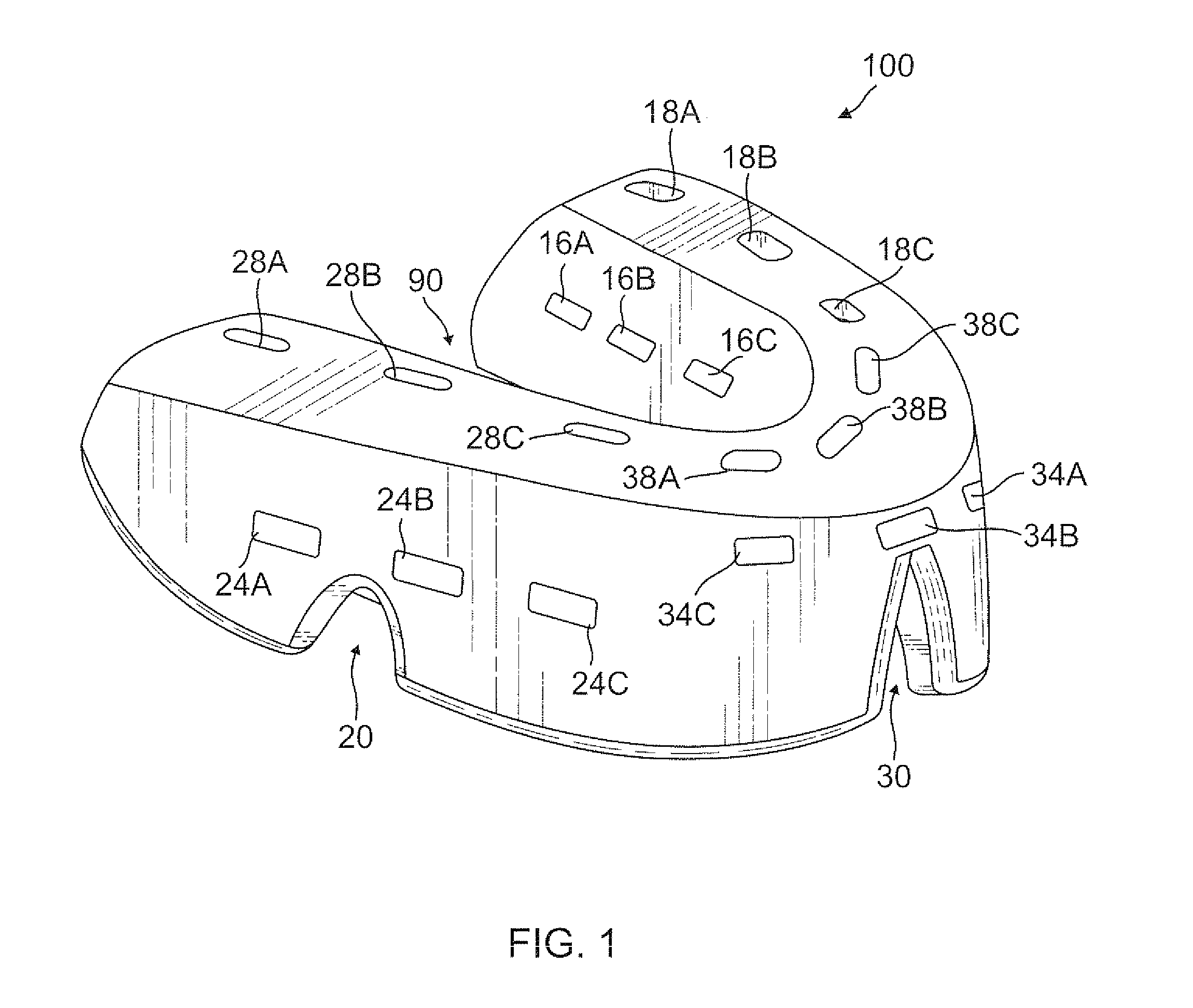
[0012]One innovation is to incorporate at least one breathing cavity in the first exterior wall of the first teeth tray section extending from the top surface into the body of the first exterior wall and extending through the transverse thickness of the first exterior wall and at least one breathing cavity in the second exterior wall of the second teeth tray section extending from the top surface into the body of the second exterior wall and extending through the transverse thickness of the second exterior wall so that an air passage is formed from outside of the mouthguard in the wearer's mouth through the breathing cavities and into the center area of the mouthguard so that air can pass to a wearer's throat.
[0014]The innovation also comprises incorporating at least one breathing cavity in the first interior wall of the first teeth tray section extending from the top surface into the body of the first interior wall and extending through the transverse thickness of the first interior wall and at least one breathing cavity in the second interior wall of the second teeth tray section extending from the top surface into the body of the second interior wall and extending through the transverse thickness of the second interior wall so that an air passage is formed through the breathing cavities and into the center area of the mouthguard so that air can pass to a wearer's throat.

Problems solved by technology

However, one problem with all mouthguards is that the athlete is not able to breathe through his / her mouth while the mouthguard is in place in the athlete's mouth.

Method used


Image

  • Mouthguard having breathing cavities and breathing holes incorporated into the body of the mouthguard
  • Mouthguard having breathing cavities and breathing holes incorporated into the body of the mouthguard
  • Mouthguard having breathing cavities and breathing holes incorporated into the body of the mouthguard

Examples


Embodiment Construction

[0035]Although specific embodiments of the present invention will now be described with reference to the drawings, it should be understood that such embodiments are by way of example only and merely illustrative of but a small number of the many possible specific embodiments which can represent applications of the principles of the present invention. Various changes and modifications obvious to one skilled in the art to which the present invention pertains are deemed to be within the spirit, scope and contemplation of the present invention as further defined in the appended claims.

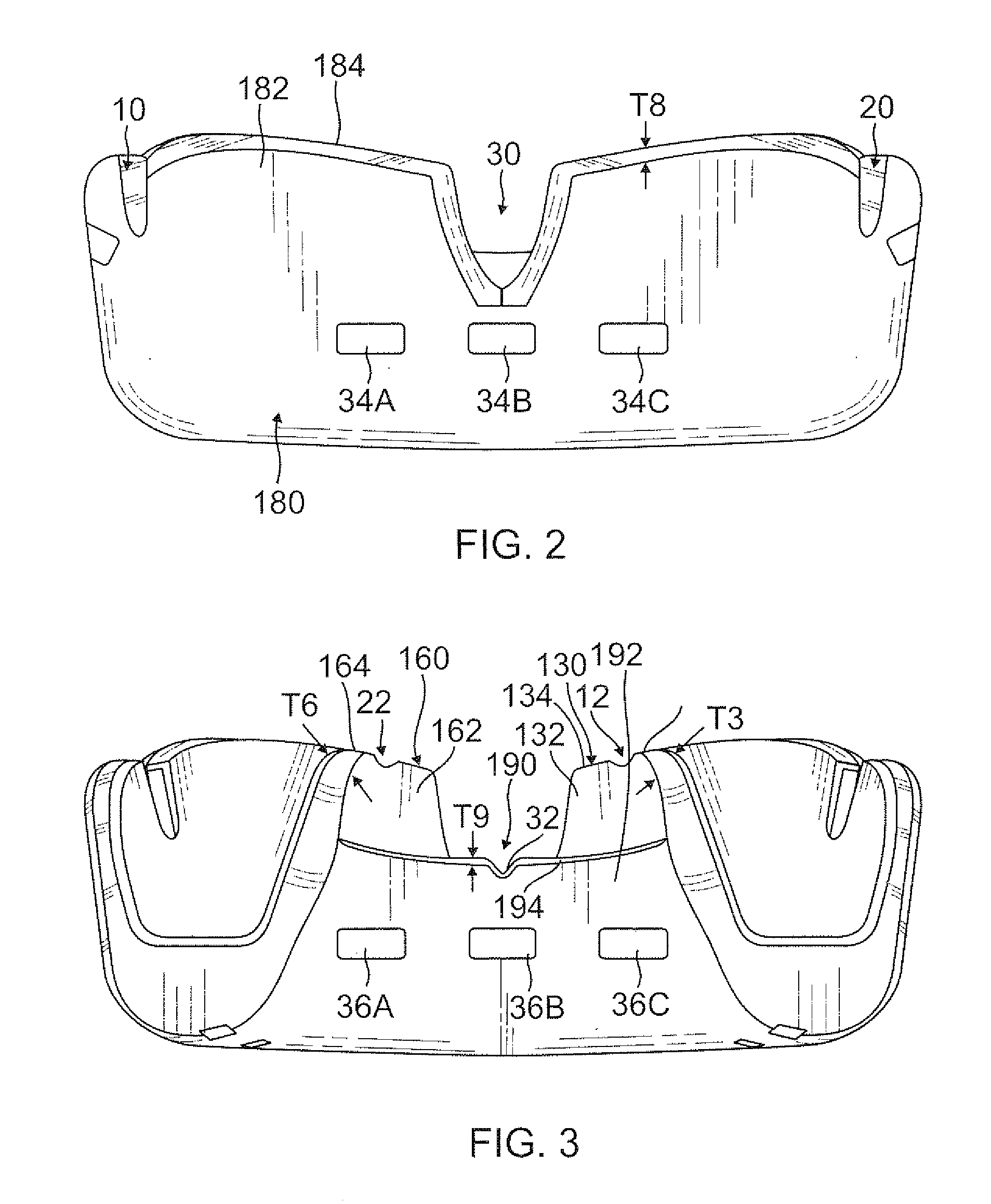
[0036]Referring to FIGS. 1-9, there is illustrated at 100 the mouthguard for protecting a wearer's upper row of teeth, which mouthguard is comprised of a teeth protecting section including a first upper teeth tray section 110 having a first transverse wall 112 of a given thickness T1 extending from an interior surface 114 to an exterior surface 116, a first exterior wall 120 having a body 122 extending upw...


PUM


Abstract

The present invention is an improved mouthguard which has incorporated into it at least one and preferably a multiplicity of breathing holes which extend through an exterior sidewall, an interior sidewall and / or through a bottom transverse wall in the body of the mouthguard. The mouthguard can also have incorporated into it at least one and preferably a multiplicity of breathing cavities extending from an upper surface of an exterior and / or interior sidewall into a portion of the sidewall to form one or more air passages.

Description

BACKGROUND OF THE INVENTION[0001]1. Field of the Invention[0002]The present invention relates to the field of mouthguards which are used by athletes during a sporting event to help protect the athlete's teeth.[0003]2. Description of the Prior Art[0004]In general, various configurations for mouthguards are known in the prior art. However, one problem with all mouthguards is that the athlete is not able to breathe through his / her mouth while the mouthguard is in place in the athlete's mouth. As a result, the athlete has to remove the mouthguard periodically, such as between plays in a football game, in order to breathe through the athlete's mouth.[0005]The present inventor has conceived of the invention of having a protruding section extending from the front of the mouthguard and extending out of the wearer's mouth so that the protruding section extends beyond the wearer's lips. The protruding section is in fluid communication with the body of the mouthguard so that the wearer can bre...

Claims


Application Information

Patent Timeline
Patent Type & Authority Applications(United States)
IPC IPC(8): A63B71/08
CPCA63B71/085
Inventor HIRSHBERG, JONATHAN
Owner JR286 TECH
Learn More