Rack frame assembly

Active Publication Date: 2012-02-02
CLOUD NETWORK TECH SINGAPORE PTE LTD
View PDF46 Cites 12 Cited by
  • Summary
  • Abstract
  • Description
  • Claims
  • Application Information

AI Technical Summary

Problems solved by technology

However, it is often inconvenient to disassemble the rack frame assembly after

Method used


Image

  • Rack frame assembly
  • Rack frame assembly
  • Rack frame assembly

Examples


Embodiment Construction

[0014]The disclosure is illustrated by way of example and not by way of limitation in the figures of the accompanying drawings in which like references indicate similar elements. It should be noted that references to “an” or “one” embodiment in this disclosure are not necessarily to the same embodiment, and such references mean at least one.

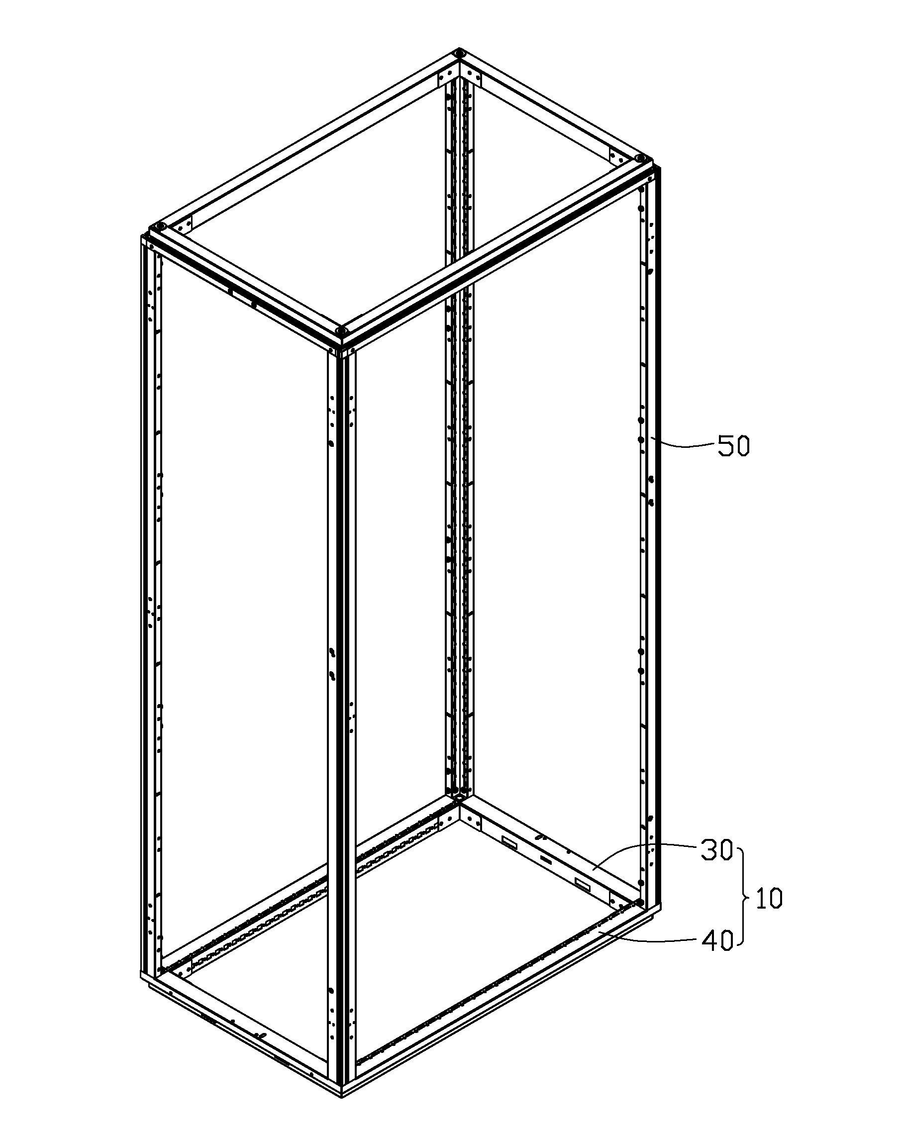
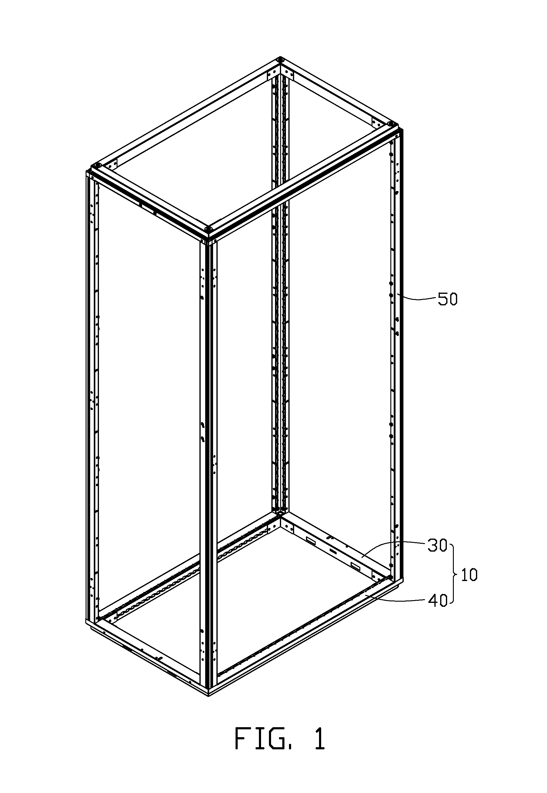
[0015]Referring to FIGS. 1, 2, and 3, a rack frame assembly in one embodiment includes two rectangular rack frames 10 and four support poles 50 connected to corners of the two rectangular rack frames 10.

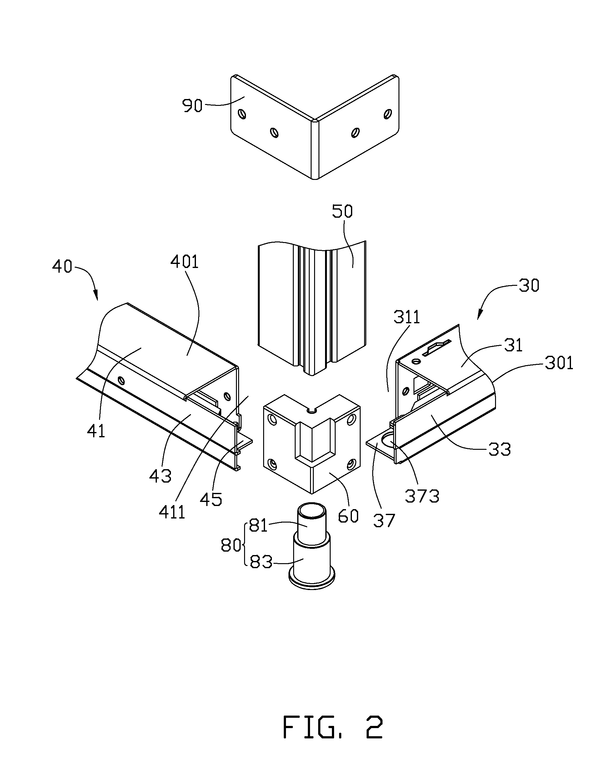
[0016]Each rectangular rack frame 10 includes a first frame pole 30 and a second frame pole 40. The first frame pole 30 includes a first end 301. The second frame pole 40 includes a second end 401, which is connected to the first end 301 of the first frame pole 30. The first end 301 includes a first top wall 31, a first bottom wall 37 parallel to the first top wall 31, and a first side wall 33 connected between the first bottom wall 37 and the fir...


PUM


Abstract

A rack frame assembly includes a first frame pole, a second frame pole, a linking member, linking post, and a support pole. A first frame pole includes a first support wall and a first through hole. The second frame pole includes a second support wall. The second frame pole is assembled with the first frame pole with the first support wall and the second support wall is located on the same plane. The linking member is located on the first support wall and the second support wall. The linking member includes a second through hole in alignment with the first through hole, and an insert portion. The linking post is located in the first through hole and the second through hole to secure the linking member to the first frame pole. The support pole includes an insert hole with the insert portion located therein.

Description

BACKGROUND[0001]1. Technical Field[0002]The present disclosure relates to a rack frame assembly for supporting servers.[0003]2. Description of Related Art[0004]A typical rack frame assembly for supporting servers usually includes two rectangular frames and four support poles connected between the two rectangular frames. Each of the support poles includes a bar for fixing peripheral devices. Each of the frames includes a first frame pole and a second frame pole, perpendicularly connected to the first frame pole. The corners of the first and second frame poles and the support pole are welded together to assemble the rack frame assembly. However, it is often inconvenient to disassemble the rack frame assembly after the first and the second frame poles are welded together with the support pole.[0005]Therefore, there is room for improvement within the art.BRIEF DESCRIPTION OF THE DRAWINGS[0006]Many aspects of the embodiments can be better understood with references to the following drawi...

Claims


Application Information

Patent Timeline
IPC IPC(8): A47B96/14
CPCH05K7/1488Y10T403/341H05K7/183H02B1/014
Inventor FAN, CHEN-LU
Owner CLOUD NETWORK TECH SINGAPORE PTE LTD
Why Eureka
Try Eureka