Electric steam generation

Inactive Publication Date: 2012-02-16
STRIX LTD
View PDF13 Cites 22 Cited by
  • Summary
  • Abstract
  • Description
  • Claims
  • Application Information

AI Technical Summary

Benefits of technology

[0010]Thus it will be seen by those skilled in the art that in accordance with the invention steam can be produced “on demand” by opening the valve to admit water into the boiler, whilst the inherent time lag is reduced by providing an initial surge of water into the boiler. The surge of water allows the boiler to be filled more rapidly than if it were simply supplied by water at the steady-state flow rate at which it can produce steam. This minimizes the delay in the user having the steam available. The surge volume, which can be considered to be the total volume of water supplied over and above what would have been supplied at the steady-state flow rate, will typically need to be less than the volume of the boiler. The surge volume might be such that when added to the “normal” flow the boiler is filled to its design capacity. In some embodiments the surge volume is at least half the volume of the boiler.
[0056]In a set of embodiments the base unit and appliance comprise means for preventing separation in a direction substantially parallel to the axis of the connection, but which permit removal of the appliance in a direction non-parallel to said axis. In such embodiments the configuration of the base and appliance prevent disconnection under the force of the pressurized water supply tending to separate the connectors and / or the contact force of the electrical connector, whilst still allowing the user to remove the appliance from the base simply picking it up in an appropriate direction. One possible way of implementing this would be to provide a recess on the base unit into which the appliance could be seated by a tilting or rotating action with the distal wall of the recess, or indeed any other mechanical arrangement, preventing movement along the connector axis, i.e. tangential to the tilting action required to place or remove the appliance Another example would be a hook or ridge on one of the appliance or the base unit cooperating with a corresponding feature on the other.

Problems solved by technology

However, the steam produced is at very low pressure (essentially ambient pressure) and cannot be produced very quickly, making it relatively ineffective.
They deliver a very high performance but are very expensive and tend to account therefore only for a very small proportion of the market.
The main disadvantage with these arrangements, commonly known as instantaneous steam generator irons, is that there is in fact a significant time lag (of the order of 10 seconds) between the user pressing a button to demand steam and the steam actually being produced and conveyed to the iron.
This significantly limits user acceptance, even though higher steam flow rates than vented steam irons can be achieved when the steam is eventually delivered.

Method used


Image

  • Electric steam generation
  • Electric steam generation
  • Electric steam generation

Examples


Embodiment Construction

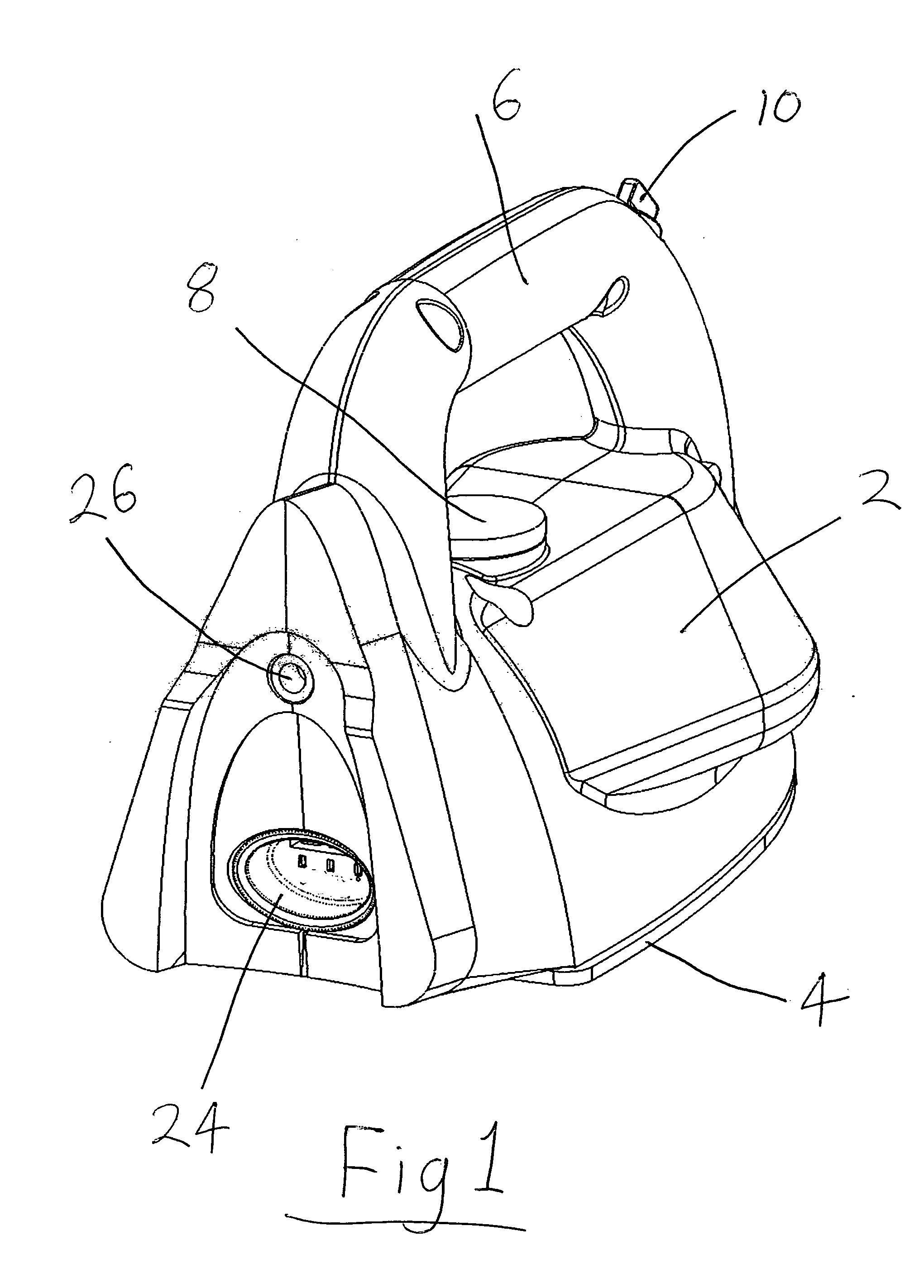
[0087]FIG. 1 is an external view of a steam iron 1 which embodies several aspects of the invention. In FIG. 1 can be seen the main body 2, an electrically heated sole plate 4 and a handle 6. A temperature selector knob 8 is provided on the body 2 beneath the handle 6. A further knob 10 is provided on the front of the handle 6 to allow a user to control the amount of steam supplied by the iron (alternatively it could simply allow steam to be switched on or off). At the rear of the iron is a cordless electrical connector 24—here the male part of the Applicant's P75 cordless electrical connector set but of course any other suitable connector could be used—and a water connector 26.

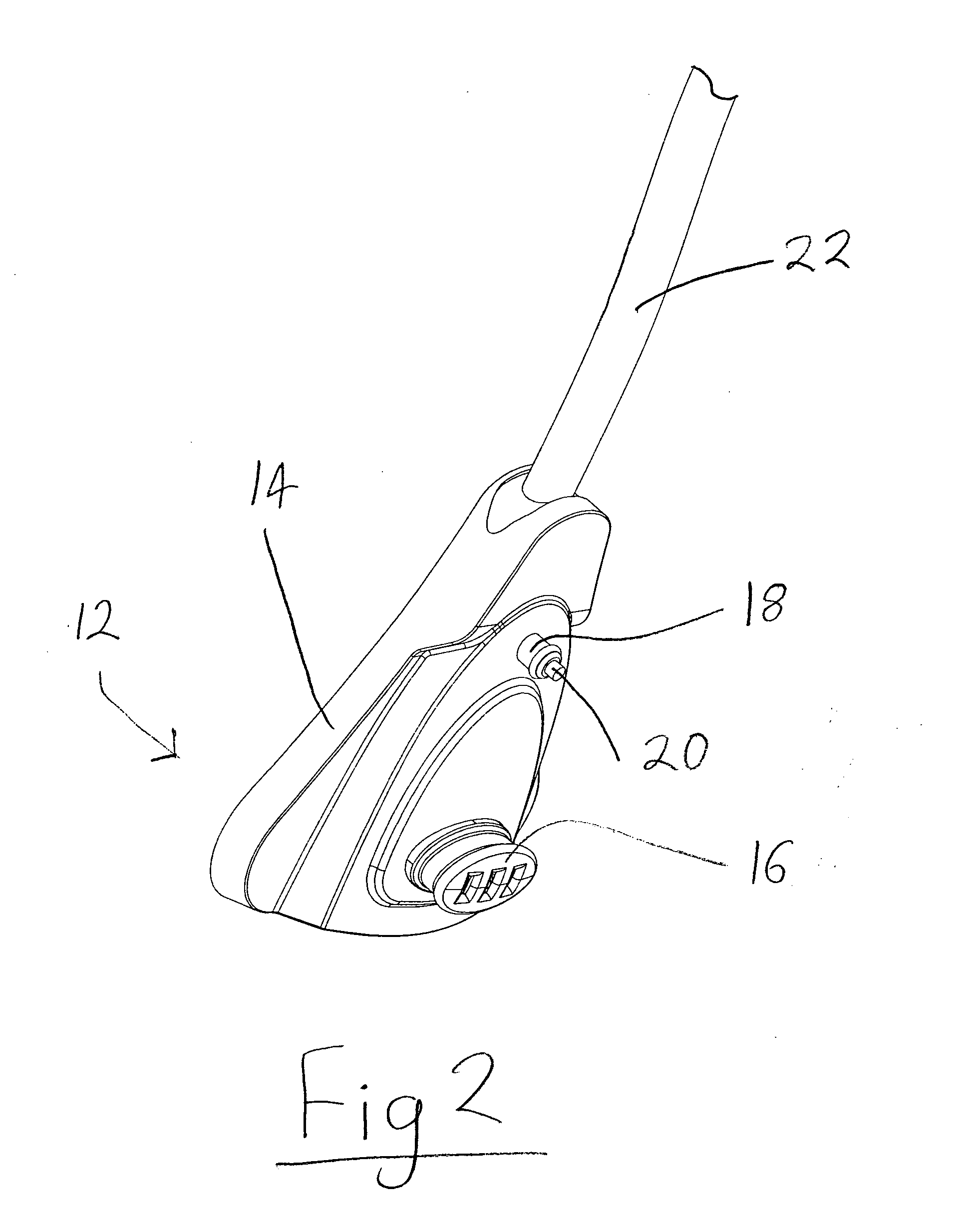
[0088]FIG. 2 shows an adaptor unit 12 for connection to the rear of the iron for supplying the iron with electrical power and water. The adaptor comprises an outer body 14. Projecting from one face of the body 14 is the female part 16 the Applicant's P75 cordless connector set. Above the electrical connector 1...


PUM


Abstract

A steam generator e.g. for a hand-held portable appliance such as a domestic iron or steam cleaner comprises a water inlet, a boiler, a valve for controlling the entry of water into the boiler and means for delivering a surge of water to the boiler when the valve is opened. Also disclosed is an adaptor for supplying electrical power to a mobile electrical appliance. The adaptor is operable in a corded mode when secured to the appliance for supplying electrical power and water while the appliance is being used; or a cordless mode when secured to a base unit such that electrical and water connection can be made by placing the appliance on or against the base unit; and broken by lifting or moving the appliance away from the base unit.

Description

[0001]This application is entitled to the benefit of, and incorporates by reference essential subject matter disclosed in PCT Application No. PCT / GB2010 / 000206 filed on Feb. 4, 2010, which claims priority to Great Britain Application No. 0901855.7 filed Feb. 5, 2009. It is also related to PCT Application No. PCT / GB2010 / 000212 filed on Feb. 4, 2010.BACKGROUND OF THE INVENTION[0002]1. Technical Field[0003]This invention relates to the electric generation of steam for use in domestic irons, steam cleaners, wallpaper strippers and other hand-held steam generating appliances and to various related components.[0004]2. Background Information[0005]Domestic steam irons have been around for a long time. They comprise a sole plate which is flat and intended to contact the item to be ironed and which is normally heated by means of a sheathed electrical resistance heater mounted to or embedded in the upper side of the sole plate. Traditionally, such irons which are designed to produce steam in o...

Claims


Application Information

Patent Timeline
IPC IPC(8): F22B1/28D06F75/14
CPCD06F75/12D06F75/14D06F79/026D06F75/22D06F79/02
Inventor COLLINSON, MARC GIBSONGIBBS, NICHOLAS EDWARDASHTON, STEVEN ANTHONYGARVEY, VINCENT JOSEPH
Owner STRIX LTD
Why Eureka
Try Eureka