
Thawing apparatus and method

Inactive Publication Date: 2009-07-09
HENSLEY CHARLES
View PDF90 Cites 9 Cited by
  • Summary
  • Abstract
  • Description
  • Claims
  • Application Information

AI Technical Summary

Benefits of technology

[0016]In another embodiment, the surface drying apparatus may be mounted in the bed of a pickup truck, thereby avoiding the need for a supplemental trailer. Alternatively, the bed of the pickup truck may be removed and the drying apparatus mounted directly upon the truck frame in lieu of a pickup truck bed.
[0017]Accordingly it is an objective of this invention to direct heated air at the driving surface to accomplish a safe and effective drying of a track surface.
[0018]It is also an objective of this invention to enable the operator of the apparatus to separate the heating and high velocity blowing operation such that the track may be dried with unheated air in occasions in which it would be advisable to do so. This feature would have particular utility in the area of drying an oil slick which has been treated with a chemical absorbent compound.
[0020]It is a further objective of this invention to be able to generate turbulent air flow at the driving surface level to enhance evaporation from the surface.
[0021]It is yet another objective of this invention to provide an economical apparatus that is economical to construct and economical to operate in terms of fuel cost.
[0022]It is a still further objective of this invention to be easy to operate and maneuver, allowing it to be backed up, turned in a relatively small radius or operated on banked turns, etc.

Problems solved by technology

When rain is experienced, a race has to be delayed or temporarily stopped, which of course, causes a considerable inconvenience for racers and spectators alike.
Although effective in drying most surfaces, the Eagle device suffers from significant drawbacks, including the very high cost of jet fuel.
The device may be adapted to use gasoline, but still suffers from the disadvantage that it uses an enormous amount of fuel in relation to the amount of area dried.
In addition, due to the nature of the device, the jet dryer functions very poorly on a banked surface such as race track turns.
Severe noise pollution is also a significant drawback.
In addition, the jet dryer is inadequate on a dirt surface as it creates an enormous amount of airborne dust.
As such, they are generally large and result in the application of a high degree of heat directly upon the surface.
These systems are largely inadequate as they can cause considerable damage to the track surface by drawing and burning petroleum components from the asphalt.
If an asphalt surface is repeatedly dried by such a means, over time, the upper surfaces of the asphalt will become brittle and deteriorate due to the drawing of oil from the asphalt.
In addition, systems featuring a direct flame cannot be used to clean up an oil spill or an oil slick caused by an accident.
Excessively high temperatures in this process may result in smoking which is the removal of some of the petroleum components of the asphalt.
All of the prior art devices described above suffer from one or more drawbacks that severely limit utility with respect to economical and effective track drying.
Many of the prior art devices utilize direct flame or excessive heat which precludes the device from being used to clean an oil spill from the track.
Furthermore, some of the devices are excessively heavy and bulky and cannot be maneuvered on a banked track.
As mentioned earlier, many of the prior art devices actually damage the surface of the asphalt tracks by drawing petroleum components from the asphalt which damages the surface over time.
In addition, the prior art devices are generally ineffective to use on drying a dirt track.

Method used


Image

  • Thawing apparatus and method
  • Thawing apparatus and method
  • Thawing apparatus and method

Examples


Embodiment Construction

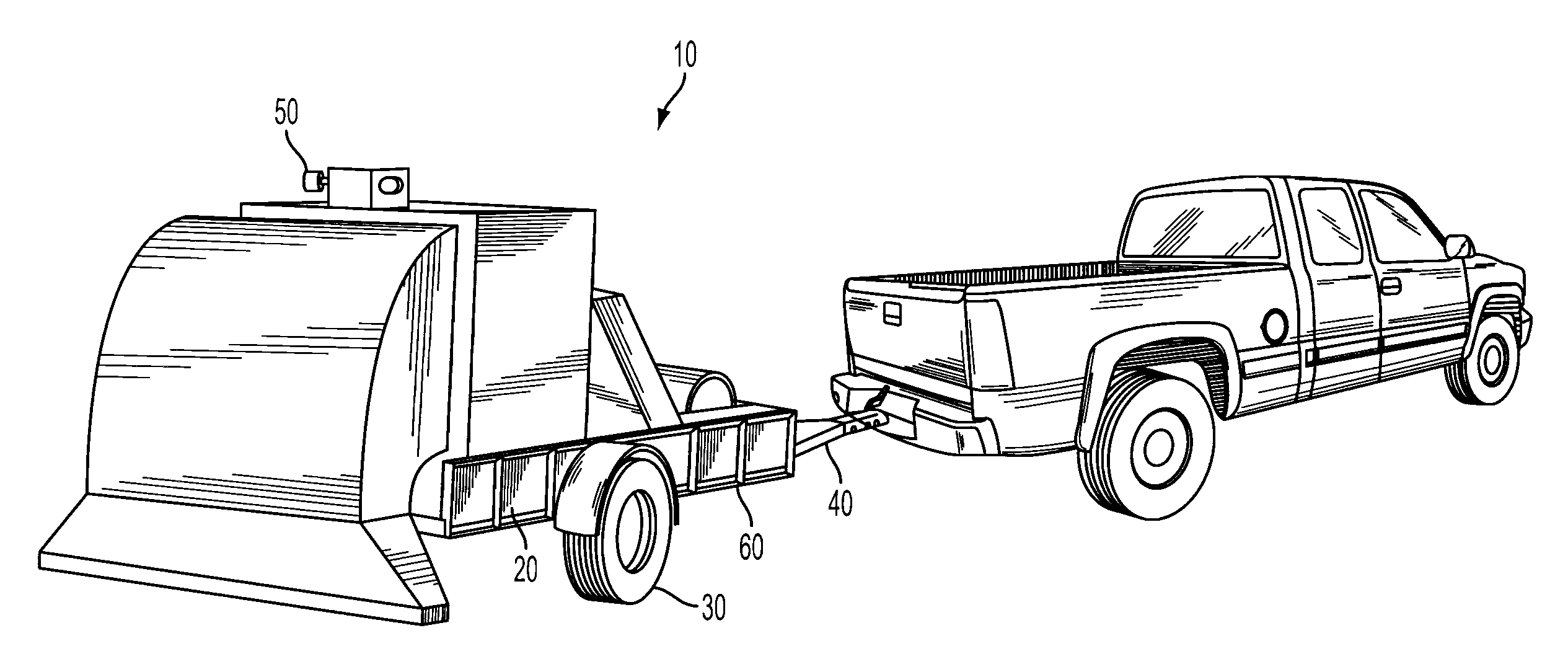
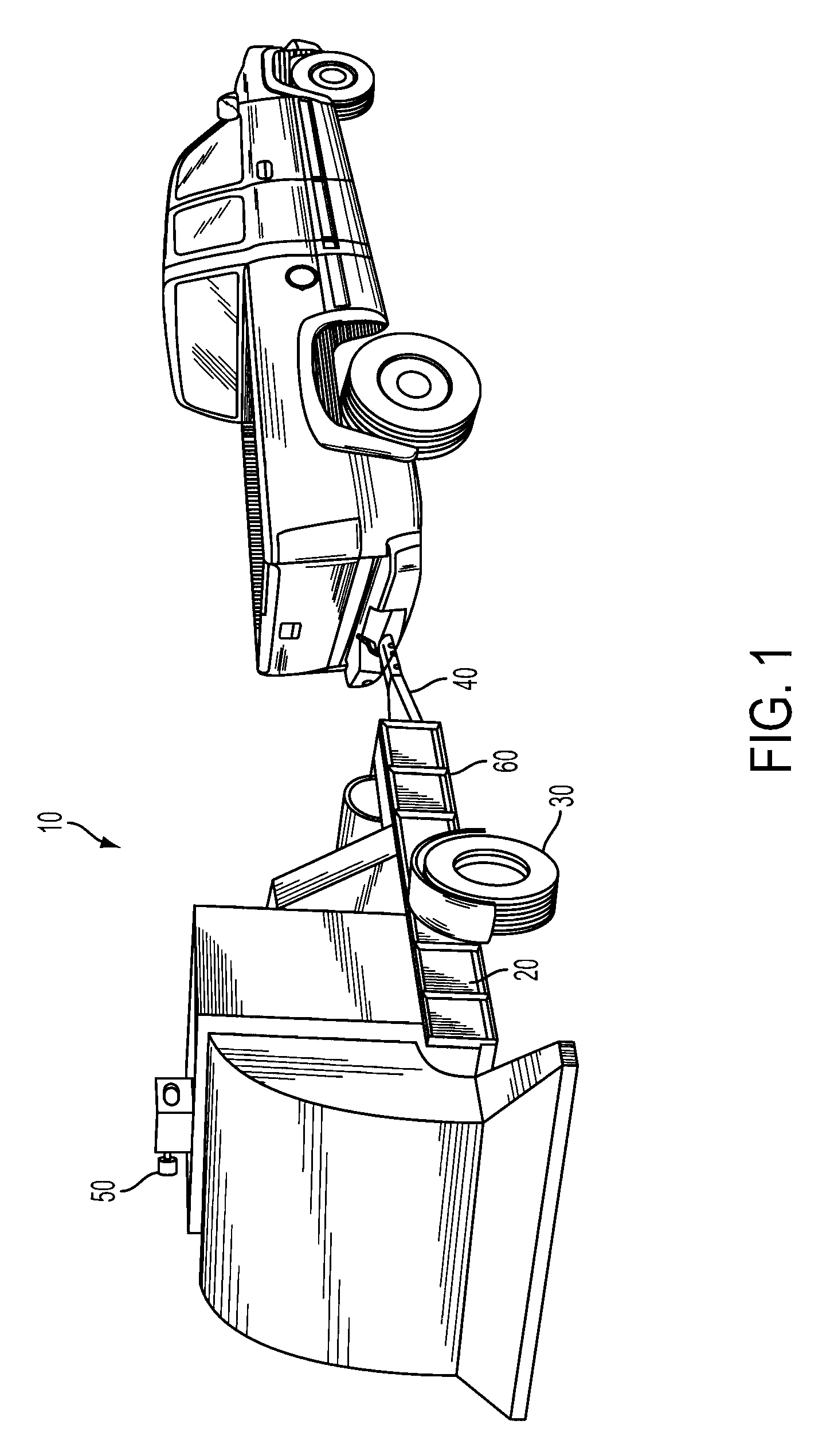
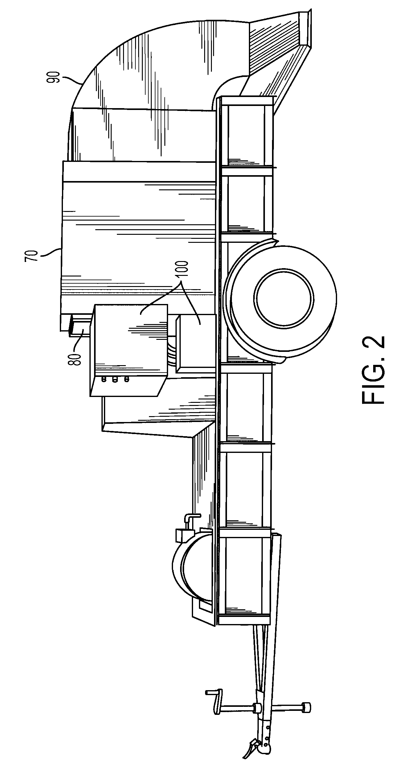
[0033]FIG. 1 shows the preferred embodiment of the ground surface drying apparatus 10. FIG. 1 illustrates the size of the preferred embodiment relative to a towing vehicle, it's ability to travel public roadways, and it's general maneuverability. The preferred embodiment is self-contained on it's own chassis 20 or frame, having two wheels 30 and a hitch 40 allowing it to be towed by any suitable vehicle such as a car, truck, or tractor, upon which all the other elements of this invention are mounted. The drying apparatus 10 is of a width and length appropriate for being towed on public roads as well as for its functional purpose and has the appropriate signals 50 etc. needed for public roads. Just above the axle of the wheels 30 is a lower deck 60 upon which most of the other elements of the invention are mounted. Around three sides of the chassis 20 are rails supported by vertical members rising up from the previously mentioned deck 60. The un-railed side is the rear of the trailer...


PUM


Abstract

An apparatus and method for quickly and effectively drying ground surfaces or thawing and melting frozen outdoor locations uses a directed air current heated by combustion in the air flow. The invention consists of a means for blowing air upon the surface, a means for heating the air and a means for moving the apparatus with respect to the surface to provide flexibility and control in the degree of drying / heating performed. The apparatus and method may be applied to a variety of surfaces including earthen (dirt) surfaces, concrete and asphalt. The apparatus and method may also be directed to thawing or melting frozen installations such as external piping, train track switches, and other electrical and mechanical targets. The embodiments of the invention are mobile and allow the application of heated air to disparate locations and targets.

Description

CROSS REFERENCE TO RELATED APPLICATIONS[0001]This application claims priority from U.S. provisional application 60 / 478,658, filed on Jun. 13, 2003 and pending U.S. patent application Ser. No. 10 / 865,960 filed on Jun. 12, 2004. The entire disclosure contained in U.S. provisional application 60 / 478,658, including the attachments thereto, and the entire disclosure contained in U.S. patent application Ser. No. 10 / 865,960 is incorporated herein by reference.BACKGROUND OF THE INVENTION[0002]1. Field of the Invention[0003]This application relates to a method and apparatus for thawing items such as earthen surfaces, asphalt, concrete driving surface, railroad tracks, external electrical and mechanical works or other outdoor items. The apparatus may also have application for drying surfaces and related purposes, as initially discussed below.[0004]2. Description of the Related Art[0005]Motorized racing has become a very popular entertainment form in the United States and abroad, drawing audie...

Claims


Application Information

Patent Timeline
IPC IPC(8): F26B3/02F26B21/00
CPCE01C23/14F26B21/001E01H5/106
Inventor HENSLEY, CHARLES
Owner HENSLEY CHARLES
Learn More