Axial-flux thin-plate motor

Inactive Publication Date: 2012-05-24
IND TECH RES INST
View PDF12 Cites 21 Cited by
  • Summary
  • Abstract
  • Description
  • Claims
  • Application Information

AI Technical Summary

Benefits of technology

[0006]The features of the axial-flux thin-plate motor can be summarized as follows. First, the annular disk-like stator is formed of a strip of silicon steel plate. The silicon steel strip is punched to form a lot of recesses along the strip, and then is tightly wound to become an annular disk. The pitch between any two adjacent recesses on the silicon steel strip must be adjusted to form stator teeth and slots with smoothly continuous tooth sides. The annular disk is then made to form a basic structure of the stator disk, with the teeth without tooth shoes thereon. The prior-art stators are formed of laminated silicon steel plates; however, the stator disk in the embodiments is fabricated by other means. A silicon steel plate is striped, punched with recesses of gradually increased pitch along the strip, and wound tightly into an annular disk. The fabrication process for the strip and the disk of silicon steel can thus be integrated, with lower cost and higher production efficiency. Second, each coil is tightly wound around outside of an insulation sleeve, and the insulation sleeves with coils are disposed on the stator teeth. Then the coils are connected and grouped into phases of the motor. Thu

Problems solved by technology

However, the traditional manufacturing process of axial-flux motors did not lead to a high slot fill ratio, so that the thickn

Method used


Image

  • Axial-flux thin-plate motor
  • Axial-flux thin-plate motor
  • Axial-flux thin-plate motor

Examples


first embodiment

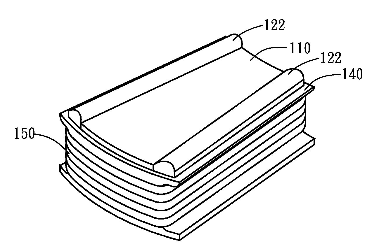
[0026]Regarding the insulation sleeve 140, several exemplary embodiments are described below. Please refer to FIGS. 5A to 5E. FIG. 5E shows the assembly structure of the tooth 110, tooth shoe 120, and insulation sleeve 140 according to the present disclosure. The insulation sleeve 140, made of plastic material, is tightly wound with the coils 150. Then the insulation sleeve 140 is disposed onto tooth 110 with a gap between the tooth 110 and the insulation sleeve 140. The gap serves as a receiving space for the tooth shoe 120 to be embedded into. The tooth shoe 120 is made in a curved shape, so that when the tooth shoe 120 is inserted into the gap, the insulation sleeve 140 is deformed slightly to fit and clip the tooth shoe 120. In this embodiment, two protrusions 121 are formed on the tooth shoe while two grooves 132 are formed on the side wall of the tooth 110 (also as shown in FIG. 4B). The grooves 132 and the protrusions121 fit and correspond to each other so as to fix the tooth...

third embodiment

[0028]Referring to FIGS. 7A and 7B, FIG. 7B shows the assembly structure of the tooth 110 and insulation sleeve 140 according to the present disclosure. In FIGS. 7A and 7B, the stator disk 100 further comprises a stator base 160 joined to the bottom of the stator disk 100. It is noted that the insulation sleeve 140 can be composed of ferromagnetic steel in this embodiment. In this example, the insulation sleeve 140 is made of stainless steel. The edge or extension of the insulation sleeve 140 is designed to exceed the top of the tooth 110 in width, and a fixer 142 such as a rivet or a solder is used to bond the insulation sleeve 140 to the stator base 160, so that the insulation sleeve 140 can be fixed to the tooth 110 without participation of the tooth shoe 120.

[0029]Wires are tightly wound around outside of each insulation sleeve 140 to form a coil 150. Then the insulation sleeve 140 with coil is disposed to surround the tooth 110, as shown in FIG. 5B, 6B, or 7B. Coils 150 are the...

fourth embodiment

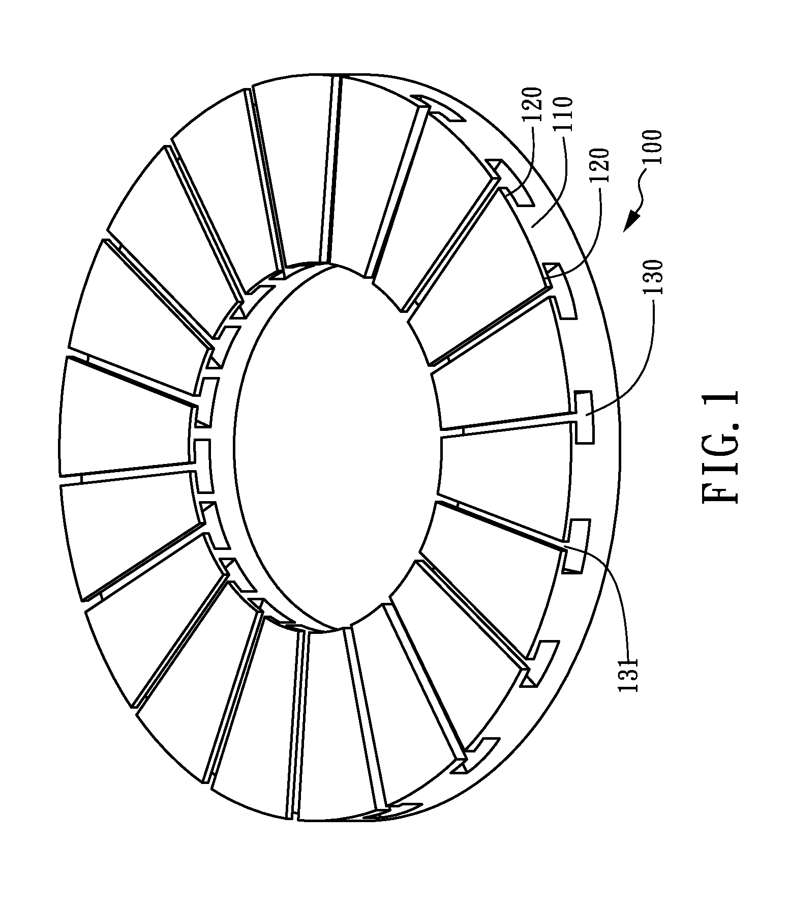
[0032]FIGS. 8A and 8B show, respectively, an exploded perspective and a perspective views for the assembly structure of the stator disk 100 according to the present disclosure. Referring to FIGS. 8A and 8B, a stator base 160 is joined to the bottom of the stator disk 100 on which the teeth 110 are shaped. The stator base 160 may be a part of the outer case. The stator base 160 may have a recess on its top to fit the bottom of the stator disk 100. The stator disk 100 may further comprise a clamp disk 170 with holes corresponding to the teeth 110, so that the clamp disk 170 can be fit to the stator disk 100 and disposed on the bottom of the tooth slots 130. Also, the clamp disk 170 can be bonded to the stator base 160 by means of soldering, riveting, or screwing. The insulation sleeve 140 is then disposed on the clamp disk 170 to assemble the stator disk 100.

[0033]From the foregoing description, the features of the axial-flux thin-plate motor according to this disclosure can be summar...


PUM


Abstract

An axial-flux thin-plate motor is disclosed, which includes: a stator formed of an annular disk of silicon steel and comprising a plurality of teeth formed on one side of the annular disk, a plurality of insulation sleeves, each insulation sleeve having a shape which matches each tooth, and a plurality of coils, each coil formed around outside of each insulation sleeve, the coils connected and grouped to form n-phase windings in accordance with a phase number n of the motor; and a rotor formed of a ferromagnetic disk with a plurality of permanent magnets embedded on one side of the ferromagnetic disk.

Description

CROSS-REFERENCE TO RELATED APPLICATION[0001]This non-provisional application claims priority under 35 U.S.C. §119(a) on Patent Application No. 099140355 filed in Taiwan R.O.C. on Nov. 23, 2010, the entire contents of which are hereby incorporated by reference.TECHNICAL FIELD[0002]The present disclosure relates to an axial-flux thin-plate motor, and more particularly, to a stator structure of the axial-flux thin-plate motor to increase its slot fill ratio and lower its torque ripple.TECHNICAL BACKGROUND[0003]Regarding conventional slim motors, the coils wound around the teeth of the motor stator are formed by a winding machine; therefore, a large slot opening is required for the winding and the slot fill ratio of the stator coils is less than 50%. To increase the slot fill ratio and lower the torque ripple, a motor stator disk can be formed by coiling a punched strip of silicon steel plate, disposing a stator coil of more than 70% slot fill ratio around the tooth on the stator disk, ...

Claims


Application Information

Patent Timeline
IPC IPC(8): H02K21/24H02K3/52H02K3/34
CPCH02K1/146H02K1/148H02K2203/12H02K21/24H02K3/522
Inventor YANG, YEE-PIENHSU, SHIH-HSINCHIEN, SHIH-HSIANG
Owner IND TECH RES INST
Why Eureka
Try Eureka