Capacitive touch panel

a capacitive touch and touch panel technology, applied in the field of capacitive touch panel, can solve the problems of affecting consequential errors in determining the touch position, and the sensitivity of the controller in determining the touched position but also so as to increase the sensitivity of the controller in determining the capacitance variation and facilitate the enlargement of the touch panel

Inactive Publication Date: 2012-06-14
MINLEAD
View PDF4 Cites 1 Cited by
  • Summary
  • Abstract
  • Description
  • Claims
  • Application Information

AI Technical Summary

Benefits of technology

[0009]An objective of the present invention is to provide a projected capacitive touch panel having lower and uniform values of internal resistance of the electrodes on the sensing layers to raise sensitivity of a controller in reading capacitance variation and facilitate enlargement of the touch panel.
[0014]As each sensing row of the X-axis sensing layer and each sensing column of the Y-axis sensing layer has multiple electrode strings parallelly connected with each other, the internal resistance of the parallelly connected electrode strings is lowered. Additionally, different numbers of X-axis electrodes and Y-axis electrodes of each row and each column can be selectively connected in parallel with each other to obtain different resistance values and adjust the values of internal resistance of each sensing row and each sensing column. Accordingly, each sensing row and each sensing column can have uniform internal resistance to facilitate enlargement of the touch panel.

Problems solved by technology

Hence, the sensitivity of the controller in reading touched positions is affected and consequential errors in determining touch positions may happen.
Therefore, the values of internal resistance of the sensing rows and the sensing columns are not uniform such that not only sensitivity of the controller in determining touched positions but also enlargement of touch panel is affected.

Method used


Image

  • Capacitive touch panel
  • Capacitive touch panel
  • Capacitive touch panel

Examples


Embodiment Construction

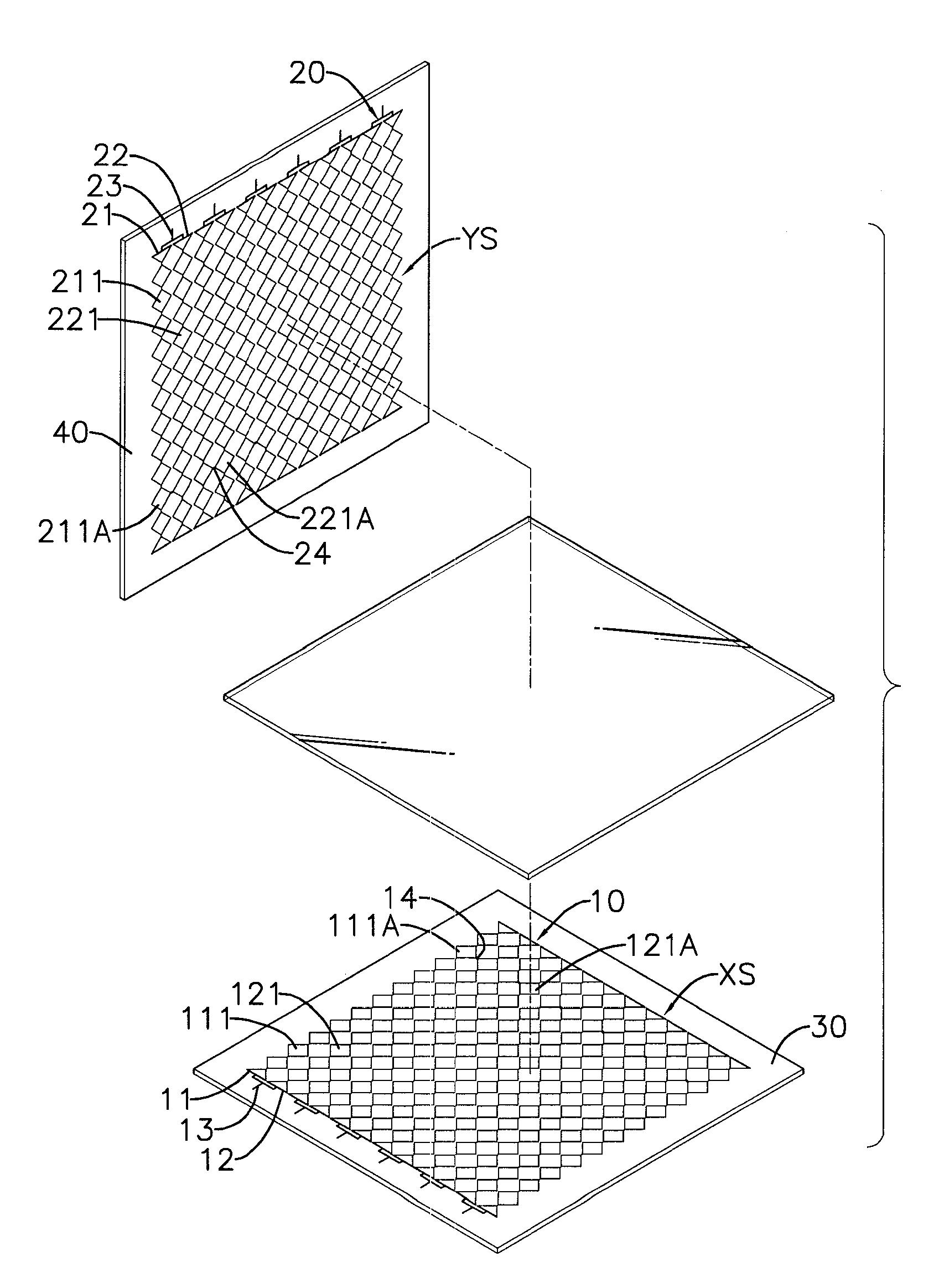
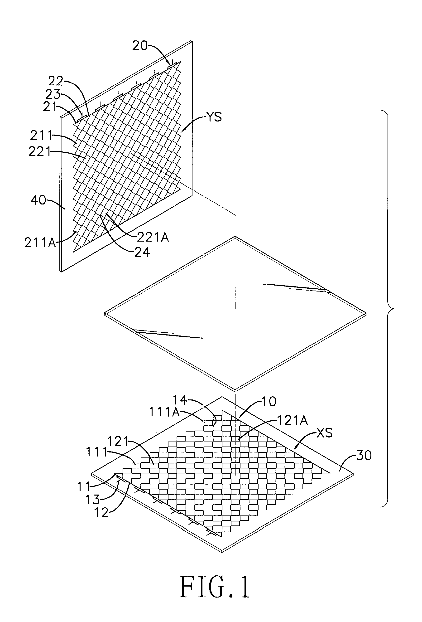
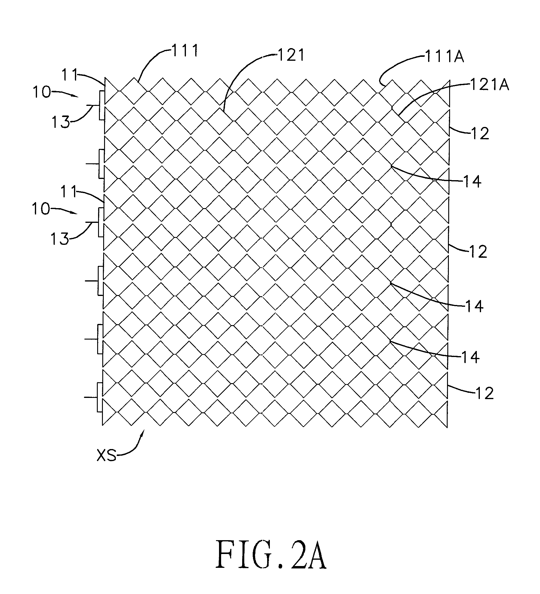
[0022]With reference to FIGS. 1, 2A and 2B, a projected capacitive touch panel in accordance with the present invention has an X-axis sensing layer XS and a Y-axis sensing layer YS.

[0023]The X-axis sensing layer XS has multiple sensing rows 10. Each sensing row 10 has an X-axis driving line 13 and multiple X-axis electrode strings 11, 12. The X-axis driving line 13 is formed on one end of the sensing row 10. In the present embodiment, each sensing row 10 includes, but not limited to, two X-axis electrode strings 11, 12. Each X-axis electrode string 11, 12 is composed of multiple X-axis electrodes 111, 121 serially connected. The two X-axis electrode strings 11, 12 have two respective X-axis electrodes 111, 121 parallelly connected. In the present embodiment, two ends of the respective X-axis electrode strings 11, 12 on a same side (left side) are parallelly connected and further connected to a corresponding X-axis driving line 13. Two adjacent X-axis electrodes 111A, 121A of the res...


PUM


Abstract

A capacitive touch panel has an. X-axis sensing layer and a Y-axis sensing layer. The X-axis and Y-axis sensing layers respectively have multiple sensing rows and sensing columns. Each sensing row or sensing column has multiple X-axis or Y-axis electrode strings. Each X-axis or Y-axis electrode string has multiple X-axis electrodes or Y-axis electrodes serially connected. The X-axis electrode strings or Y-axis electrode strings are connected in parallel with each other. The Y-axis electrodes are alternately or directly aligned with the X-axis electrodes. With the foregoing design, the resistance of each row and column can be effectively reduced so as to raise the reading sensitivity of a controller and maintain uniform internal resistance for each sensing row and column to facilitate enlargement of the capacitive touch panel.

Description

BACKGROUND OF THE INVENTION[0001]1. Field of the Invention[0002]The present invention relates to a capacitive touch panel, and more particularly to a projected capacitive touch panel having lower and uniform values of internal resistance of the electrodes on the sensing layers.[0003]2. Description of the Related Art[0004]With reference to FIG. 4, a conventional projected capacitive touch panel has a substrate 70, an X-axis sensing layer 80 and a Y-axis sensing layer 90. The substrate 70 is transparent. The X-axis sensing layer 80 is formed on a top surface of the substrate 70 and has multiple horizontal sensing rows. Each sensing row has multiple rhombic X-axis electrodes 81 serially connected to each other and is connected with an X-axis driving line 82.[0005]The Y-axis sensing layer 90 is formed on a bottom surface of the substrate 70 and has multiple vertical sensing columns. Each sensing column has multiple rhombic Y-axis electrodes 91 serially connected to each other and is con...

Claims


Application Information

Patent Timeline
Patent Type & Authority Applications(United States)
IPC IPC(8): G06F3/045
CPCG06F3/044G06F3/0445
Inventor HSU, JANE
Owner MINLEAD
Why Eureka
Try Eureka