Inductive position sensor with secondary turns extending through a printed circuit board

a technology of printed circuit board and inductive position sensor, which is applied in the direction of converting the output of the sensor electrically/magnetically, instruments, etc., can solve the problems of tilting along the length of the sensor, and achieve the effect of facilitating the use of voltage measurements, optimizing the number of turns over a given area, and constant longitudinal offset between two turns

Active Publication Date: 2020-10-27
VITESCO TECH GERMANY GMBH
View PDF8 Cites 0 Cited by
  • Summary
  • Abstract
  • Description
  • Claims
  • Application Information

AI Technical Summary

Benefits of technology

[0020]This allows the sensitivity to variation in airgap and the sensitivity to variation in eccentricity to be greatly decreased and the linearity of the sensor to be enhanced.
[0022]Moreover, since each turn passes through the printed circuit board four times, it is better anchored in place and the turns are not at risk of moving either longitudinally or laterally with respect to the printed circuit board.
[0028]Advantageously, the connection between the end of the longitudinal edge of the first portion of the first sector and the fourth via and the connection between the end of the longitudinal edge of the first portion of the second sector and the second via are in one and the same plane that is parallel to the printed circuit board, the second and fourth vias being of the same length. This makes it possible to have a symmetry contributing to the balance of the turn.
[0031]Advantageously, the first and second sectors are equal in length and the offset in the longitudinal direction between two neighboring turns is smaller than the length of the first or of the second sector. This makes it possible to optimize the number of turns over a given area.
[0032]Advantageously, the longitudinal offset between two turns is constant. This makes it possible to facilitate the use of the voltage measurements taken at the terminals of the secondary windings.

Problems solved by technology

The problem with this turn is its tilted appearance along its length.

Method used


Image

  • Inductive position sensor with secondary turns extending through a printed circuit board
  • Inductive position sensor with secondary turns extending through a printed circuit board
  • Inductive position sensor with secondary turns extending through a printed circuit board

Examples


Embodiment Construction

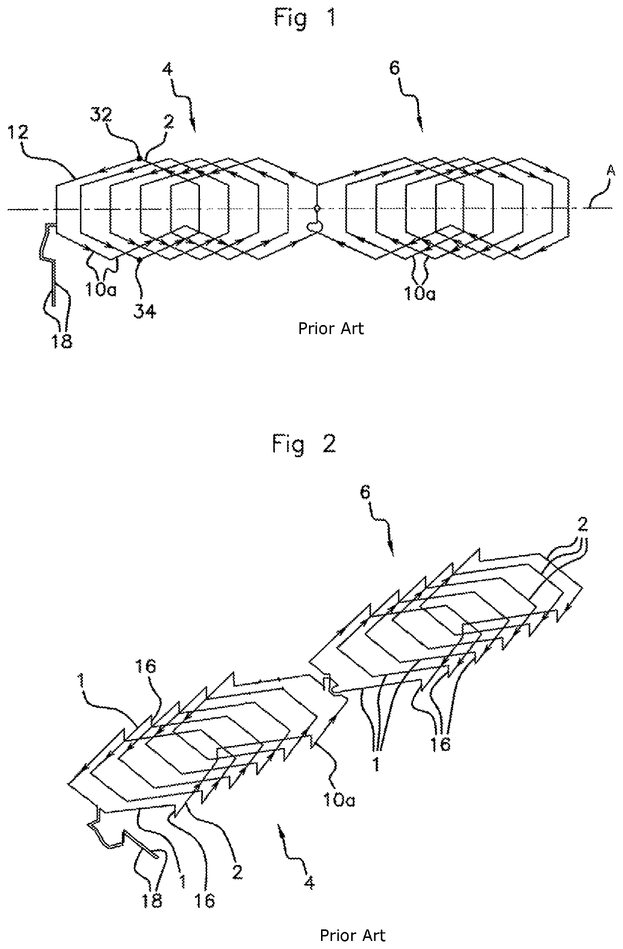
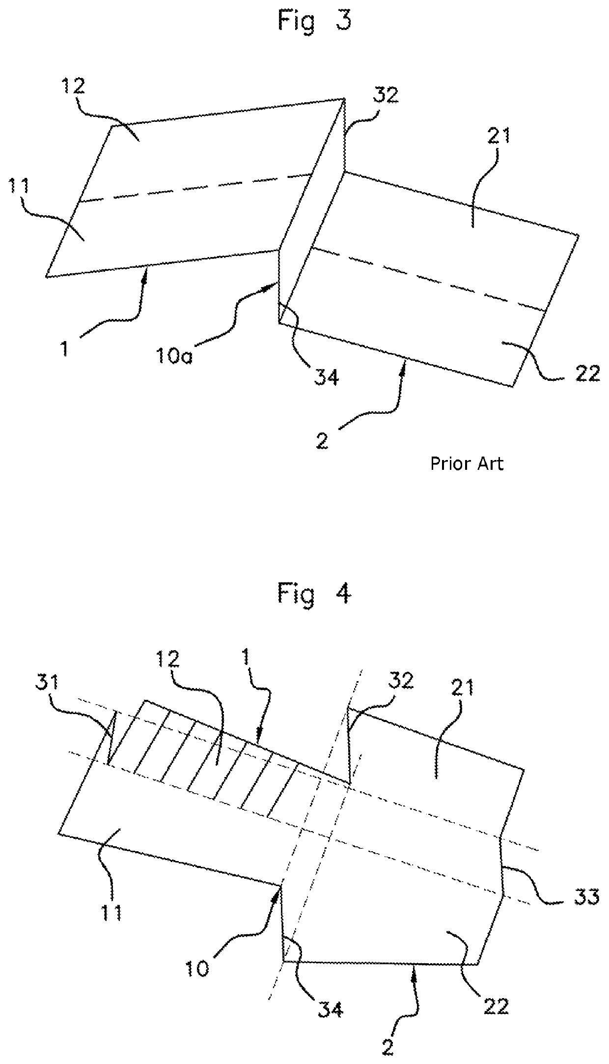
[0042]FIG. 1 shows a view from above of a first secondary winding 4 and a second secondary winding 6 and FIG. 2 is a perspective view of the secondary windings of FIG. 1. Each of these two windings has turns 10a. These turns 10a are in accordance with the prior art but FIG. 1 and FIG. 2, which is described below, may be used to illustrate an aspect of the present invention if the shape of the turns 10a is disregarded, and only for the stacked arrangement of the turns 10a.

[0043]It should be noted that for each of these windings, the turns 10a are all substantially similar, but are offset each time with respect to one another in a longitudinal direction illustrated in FIG. 1 by a longitudinal axis A.

[0044]The longitudinal offset between two neighboring turns may be the same each time. Furthermore, and again preferably, the second secondary winding 6, is, when seen from above, symmetrical with respect to the first secondary winding 4 in relation to a transverse plane (not shown) that ...


PUM

PropertyMeasurementUnit
lengthaaaaaaaaaa
widthaaaaaaaaaa
magnetic fluxaaaaaaaaaa

Abstract

An inductive position sensor including at least two secondary windings consisting of a plurality of turns that are formed on two opposite faces of a printed circuit board and divided into first and second sectors. The first and second sectors are divided, in one turn width, into a first portion on one face of the printed circuit board and a second portion on an opposite face. The second portion of the first sector is extended by a first portion of the second sector and the first portion of the first sector is connected to the second portion of the second sector of a neighboring turn. The portions are connected pairwise by a respective via passing through the printed circuit board.

Description

CROSS REFERENCE TO RELATED APPLICATIONS[0001]This application is the U.S. National Phase Application of PCT International Application No. PCT / FR2018 / 051595, filed Jun. 28, 2018, which claims priority to French Patent. Application No. 1756115, filed Jun. 30, 2017, the contents of such applications being incorporated by reference herein.FIELD OF THE INVENTION[0002]The present invention relates to an inductive position sensor.BACKGROUND OF THE INVENTION[0003]This type of sensor has the advantage of making it possible to determine the position of a mechanical part, or of any other element, without requiring contact with the part of which it is desired to ascertain the position. This advantage is such that these sensors have numerous applications in a wide variety of industries. Such sensors are also used in consumer applications such as, for example, the automotive field, within which the present invention is preferably implemented. However, the invention may be used in a wide variety o...

Claims


Application Information

Patent Timeline
Patent Type & Authority Patents(United States)
IPC IPC(8): G01B7/14G01D5/20G01B7/30G01D5/22H01F17/00
CPCG01B7/30G01D5/2291G01D5/2053H01F17/0013G01D5/204
Inventor FONTANET, ALAIN
Owner VITESCO TECH GERMANY GMBH
Why Eureka
Try Eureka